



Marine Watermaker Knowledge Base
Practical technical guidance for planning, building, installing, operating, maintaining and upgrading marine reverse osmosis systems.
This Knowledge Base follows the complete watermaker process, from the seawater intake and feed system to high-pressure operation, membranes, freshwater quality control and flushing. Each section explains how the components work, how they should be selected and installed, and what to check when performance is not as expected.
The content is based on real marine installations, BlueGold components and the questions we receive from boat owners, DIY builders and technicians. It will continue to grow as new systems, components and practical topics are added.
Use the form below to send us your technical question. Questions that may also help other watermaker owners will be reviewed and may be added to this Knowledge Base as a new FAQ.
Before submitting your question, please browse the topic index and existing FAQs. When possible, include useful details such as your watermaker type, pump flow, membrane configuration, operating pressure, seawater temperature and the behaviour you are trying to understand.
Knowledge Base Topics
Getting Started
Start here if you are planning a new marine watermaker, evaluating a DIY system or trying to understand which components are required.
A marine watermaker is a reverse osmosis system designed to convert seawater into freshwater suitable for normal onboard use. It allows a boat to produce its own water while cruising, reducing dependence on marina supplies, storage capacity and bottled water.
The system draws seawater from outside the boat, removes suspended particles through one or more prefilters, and then raises the water to the pressure required by a seawater reverse osmosis membrane.
💧 The Three Main Water Streams
- Feed water: The seawater entering the system from the boat’s intake.
- Product water or permeate: The freshwater that passes through the membrane.
- Brine or concentrate: The remaining seawater, now containing a higher concentration of salts, which is discharged overboard.
A marine watermaker normally includes a seawater intake, strainer, feed pump, prefilters, high-pressure section, reverse osmosis membrane, pressure vessel, pressure control, flow measurement and a method of checking freshwater quality before sending it to the boat’s tank.
⚙️ What Determines Its Performance?
Freshwater production is influenced by several factors, including membrane size, seawater temperature, salinity, operating pressure, feed flow and membrane condition. For this reason, the production stated by a membrane manufacturer under laboratory conditions may differ from the amount produced onboard.
⛵ Why Install One Onboard?
- Greater independence during long passages or remote cruising.
- Less need to carry large quantities of freshwater.
- Reduced reliance on marina water quality and availability.
- More flexibility for showers, cooking, cleaning and daily life onboard.
- The possibility of producing freshwater whenever seawater and sufficient power are available.
When correctly designed and maintained, it becomes one of the most useful systems on a cruising boat.
Yes. A conventional marine watermaker can be assembled from individual components, and for many boat owners a modular DIY system is a practical and realistic project.
A watermaker is not a mysterious sealed appliance. It is a combination of pumps, filters, valves, hoses, instruments, electrical components and a reverse osmosis membrane arranged in the correct sequence.
🔩 Main Components of a DIY System
A typical conventional watermaker may include:
- A seawater intake and strainer.
- A low-pressure feed pump.
- One or more prefilter housings.
- A high-pressure pump and suitable motor.
- A seawater reverse osmosis membrane.
- A pressure vessel.
- A pressure gauge and regulating valve.
- High-pressure hoses and rated fittings.
- A product-water flow meter.
- A salinity or TDS monitoring system.
- A freshwater diversion arrangement.
- Electrical protection, switches, relays or control electronics.
🧰 What Skills Are Required?
Most of the work involves normal onboard installation tasks: mounting pumps and filters, routing hoses, tightening fittings, connecting electrical cables and testing the system for leaks and correct operation.
If you are already comfortable installing equipment such as a bilge pump, deck-wash pump, battery charger, filter housing or control panel, much of the process will feel familiar.
⚠️ What Requires Particular Attention?
- High-pressure safety: All pressure-side components must be correctly rated and installed.
- Component compatibility: Pump flow, membrane capacity, vessel size and motor power must match.
- Electrical sizing: Cable sections, fuses, relays and switching devices must suit the motor load.
- Correct sealing: Not every threaded connection uses PTFE tape or liquid sealant.
- Water quality control: Product water must be checked before it is sent to the freshwater tank.
- Service access: Filters, pumps, valves and membranes must remain accessible after installation.
📘 Manual or Automated?
A first DIY system can be completely manual, with pressure adjustment, flushing and product-water diversion controlled directly by the operator. Automation can later be added through sensors, relays, motorised valves or a dedicated control system such as N.E.R.D.
✅ Is DIY the Right Choice for Everyone?
A DIY system is a good option for owners who want to understand their equipment, choose standard components and remain capable of maintaining and repairing the installation while cruising.
A complete ready-made system may be preferable when installation time is limited, when a pre-engineered frame is required, or when the owner prefers a fully assembled and tested solution.
With correctly matched components, clear instructions and careful installation, a DIY system can be reliable, serviceable and specifically adapted to the layout of your boat.
Selecting the right watermaker is essential for ensuring comfort and freshwater independence during your voyages. The ideal system should match your crew’s daily consumption, preferred operating time, available power, installation space and maintenance requirements.
💧 1. Assess Your Daily Water Needs
Start by estimating how much freshwater your crew normally uses each day.
- Basic consumption: Drinking and cooking typically require around
6–8 litres (1.5–2 gallons) per person per day. - Moderate usage: Including showers and dishwashing, allow approximately
20–30 litres (5–8 gallons) per person per day. - High consumption: Laundry, frequent showers or deck washing may increase demand to
40–60 litres (10–15 gallons) per person per day.
120 litres (32 gallons) of freshwater per day.
⏳ 2. Determine Your Preferred Production Time
Decide how many hours per day you want the watermaker to operate. The same daily requirement can be met by a larger unit running for a short time or by a smaller unit operating for several hours.
- Short operating periods: To produce 120 litres in two hours, you need a system rated at approximately
60 litres per hour. - Longer operating periods: A system producing around
20 litres per hour can meet the same requirement when operated for approximately six hours.
🔋 3. Evaluate the Available Power
Marine watermakers can be powered in several different ways.
- 12 V or 24 V DC systems: Suitable for boats with adequate battery capacity, alternator charging or solar generation. They are commonly used for lower and medium production rates.
- Energy recovery systems: Designed to reduce electrical consumption and particularly useful where battery power is limited.
- 110 V or 230 V AC systems: Normally powered by an onboard generator or a suitably sized inverter. These systems can support larger motors and higher production rates.
- Engine-driven systems: Use mechanical power from the main engine and can provide high output, but normally operate only while the engine is running.
📐 4. Consider the Installation Space
Watermakers are available as modular systems or as complete frame-mounted units.
- Modular systems: Pumps, filters, pressure vessels and controls can be installed separately. This provides greater flexibility in machinery spaces with an irregular shape.
- Compact frame-mounted units: These may appear easier to install, but the complete assembly can be bulky and difficult to move through narrow lockers or access openings.
🧰 5. Factor in Maintenance and Reliability
A well-designed system should be straightforward to service, particularly when cruising far from specialised technicians.
- Pre-filtration: Protects the feed pump, high-pressure pump and membrane from suspended particles.
- Membrane care: Regular freshwater flushing, correct preservation and occasional chemical cleaning help maintain performance.
- Service access: Filter housings, pump heads, valves and electrical components should be easy to reach.
- Spare parts: Systems using widely available, non-proprietary components are generally easier to repair while cruising.
💶 6. Consider the Overall Budget
The cost of a pre-assembled marine watermaker depends on production capacity, motor type, control system, automation level and installation equipment.
- Entry-level systems: Smaller systems producing approximately 20–30 litres per hour may begin around
€5,000–€7,000. - Medium-capacity systems: Units producing approximately 60–100 litres per hour may cost around
€10,000–€15,000. - High-capacity or highly automated systems: Systems exceeding 100 litres per hour may cost
€20,000 or more.
Prices vary considerably depending on configuration, accessories and installation requirements. A DIY or modular system can provide greater flexibility, allowing components and automation levels to be selected individually.
📊 Quick Capacity Guide
| Crew size | Estimated daily need | Preferred run time | Suggested output |
|---|---|---|---|
| 2 people | 60–120 litres | 2–4 hours | 30-60 litres/hour |
| 4 people | 120–240 litres | 2–4 hours | 60-90 litres/hour |
| 6 people | 180–360 litres | 2–4 hours | 90-150 litres/hour |
It is the system that can reliably meet your daily freshwater needs while remaining compatible with your boat’s energy supply, available space, maintenance routine and cruising plans.
Not all marine watermakers operate in the same way. One of the most important design choices is whether to use a conventional direct-drive high-pressure pump or an energy recovery system based on a Clark Pump. Both solutions are supported within the BlueGold product range, but they differ significantly in power consumption, hydraulic layout, operating characteristics and component selection.
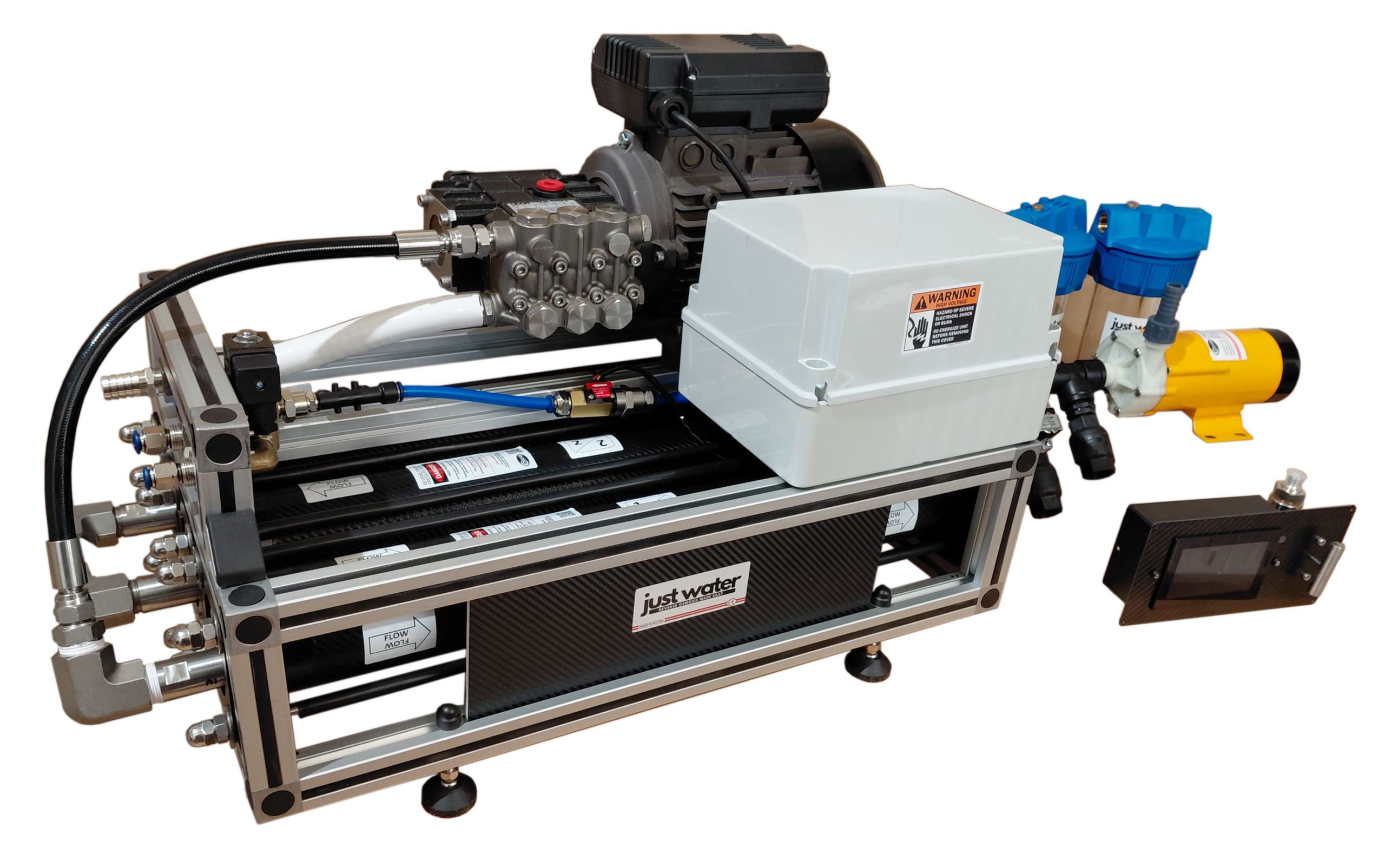
⚙️ 1. Traditional Watermakers
Traditional watermakers use an electrically or mechanically driven high-pressure pump to force seawater through a reverse osmosis membrane. Pressure is normally regulated with a needle valve installed on the brine discharge line.
This configuration is straightforward, widely understood and easy to assemble using standard marine RO components.
⭐ Main Benefits
- Simple operating principle: The hydraulic circuit is easy to understand, inspect and troubleshoot.
- Widely available components: Pumps, motors, valves, gauges and fittings can be sourced from established industrial and marine suppliers.
- Proven marine technology: Direct-drive high-pressure systems have been used successfully for decades.
- Modular construction: Components can be installed separately to suit the available onboard space.
- Wide production range: Traditional systems can be configured for anything from modest output to large-capacity installations.
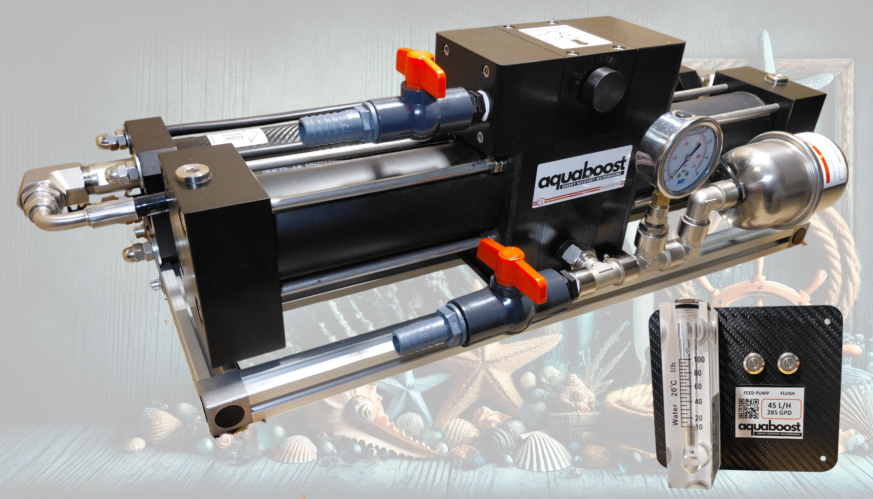
Watermaker running a third-generation enhanced Clark Pump ElectroMaax. This device is assembled by us with the new compact 3″x 21″ vessels manufactured by CobrAm in Austria. This watermaker can be easily assembled by anyone by following our instructions.
♻️ 2. Clark Pump Energy Recovery Systems
A Clark Pump is an energy recovery pressure intensifier designed specifically for reverse osmosis systems. Instead of discarding all the pressure energy contained in the brine stream, it recovers a large part of that energy and uses it to pressurise incoming seawater.
This considerably reduces the electrical power required to produce freshwater, making Clark Pump systems particularly attractive for battery-powered and solar-supported boats.
⭐ Main Benefits
- Very low electrical consumption: Particularly valuable on boats relying on batteries, alternators and solar charging.
- Efficient use of brine energy: Pressure energy that would otherwise be discharged overboard is recovered and reused.
- Quiet operation: The system does not require a large conventional high-pressure motor and pump assembly.
- Compact hydraulic concept: Well suited to energy-conscious cruising boats where power availability is limited.
- Stable membrane operation: Correctly configured systems provide controlled pressure and flow for consistent RO performance.
- Supported by BlueGold: Clark Pump components can be integrated into complete systems or selected as part of a DIY build.
🛠️ 3. Is a Clark Pump System Difficult to Build?
Building a Clark Pump watermaker is not inherently difficult, but it requires a different hydraulic layout from a conventional high-pressure pump system. The feed flow, membrane configuration, brine connections and valve arrangement must all match the operating requirements of the energy recovery unit.
BlueGold component selections and layout recommendations are designed to make the process manageable even for first-time builders. Once the operating principle is understood, the installation can be assembled in a logical sequence using standard filters, hoses, fittings, membrane vessels and control components.
⚖️ 4. Traditional System or Clark Pump?
| Feature | Traditional High-Pressure Pump | Clark Pump System |
|---|---|---|
| Electrical consumption | Moderate to high, depending on capacity | Very low |
| Hydraulic layout | Simple and conventional | Specialised energy recovery circuit |
| Component availability | Very broad | More specialised |
| Ease of troubleshooting | Generally straightforward | Requires understanding of cycling and recovery operation |
| Suitable power sources | DC motor, AC motor, generator, inverter or engine drive | Usually battery, alternator or solar-supported DC operation |
| Typical priority | Simplicity, output and serviceability | Maximum energy efficiency |
🧭 5. What BlueGold Recommends
There is no single system that is best for every boat. The right choice depends on how much water you need, how much electrical power is available and how you prefer to operate and maintain the equipment.
- Choose a traditional high-pressure pump system when you prioritise simplicity, modular construction, standard components and straightforward servicing.
- Choose a Clark Pump energy recovery system when minimising electrical consumption is the main priority, especially on battery- and solar-powered boats.
Traditional systems offer maximum flexibility and familiar components, while AQUABOOST systems with Clark Pump technology are designed for highly efficient freshwater production with minimal electrical demand.
Building a marine watermaker does not require a fully equipped workshop. In most cases, a basic onboard toolkit, a little patience and careful attention to the installation instructions are enough to complete the job.
One of the advantages of assembling a modular watermaker is that the work can normally be completed using standard tools already found on many sailing boats and motor yachts. BlueGold systems are designed around practical components, straightforward mounting methods and commonly available fittings.
You do not need custom fabrication equipment or specialised marine machinery. Our manuals and diagrams identify the tools required at each stage, and many operations are as simple as cutting a hose cleanly, tightening a fitting or securing a component to a bulkhead.
Before buying anything new, check the tools already onboard. You may already have most of what is required, and the few additional items are generally inexpensive, easy to store and useful for future maintenance.
🔧 1. Recommended Hand Tools
The following tools are sufficient for most mechanical assembly and installation work.
- Allen and hex keys: For brackets, pump mounts and components using socket-head fasteners.
- Open-ended and adjustable wrenches: For tightening fittings, valves, hose tails and mounting hardware.
- Flathead and Phillips screwdrivers: For electrical terminals, control panels, clamps and general assembly.
- Pliers and side cutters: Useful for cable ties, terminals and general installation work.
- Socket set: Helpful for motors, pumps, frames and larger mounting bolts.
🪛 2. Drilling, Cutting and Mounting Tools
- Cordless drill and drill bits: For mounting filters, pumps, brackets and control components.
- Hole saws: Useful when installing hoses, cable glands or panel-mounted instruments.
- PEX or plastic tubing cutter: Produces clean, square cuts on plastic tubing and small hoses.
- Sharp utility knife: Suitable for trimming flexible hose when used carefully.
- File or deburring tool: Removes sharp edges after cutting panels, brackets or tubing.
- Tape measure and marker: Essential for planning hose routes and component locations before drilling.
⚡ 3. Basic Electrical Tools
Electrical requirements depend on whether the system uses a low-voltage DC motor, AC motor, sensors, relays or an automatic control panel.
- Digital multimeter: For checking supply voltage, polarity, continuity and basic electrical troubleshooting.
- Wire stripper: For preparing conductors without damaging the copper strands.
- Terminal crimping tool: For producing reliable electrical connections.
- Heat gun: Optional, but useful for adhesive-lined heat-shrink terminals and protective sleeving.
- Cable ties and cable-tie cutter: For organising wiring and keeping it clear of hot, wet or moving components.
🪣 4. Priming, Flushing and Testing Items
- Bucket or clean container: Useful during priming, flushing, cleaning and commissioning.
- Clean measuring jug: Helps verify product-water flow during initial testing.
- Absorbent cloths or paper towels: Useful for identifying small leaks around fittings.
- Temporary drain hose: Allows product water and flushing water to be directed safely during commissioning.
- Flashlight or inspection lamp: Essential in dark lockers and machinery spaces.
🛢️ 5. Lubricants
The correct lubricant protects seals and makes assembly easier without damaging elastomers or contaminating the system.
- Silicone grease: Use a small amount of suitable silicone grease on membrane and pressure-vessel O-rings where instructed.
🧴 6. Thread-Sealing Products
Different fittings require different sealing methods. Some threads seal on the thread itself, while others seal with an O-ring, gasket, cone or compression surface and must not be covered with thread sealant.
- PTFE tape: Commonly used on suitable tapered plastic or brass threaded fittings.
- Loctite 55: Thread-sealing cord suitable for many metal and plastic threaded connections when used according to the manufacturer’s instructions.
- Loxeal anaerobic sealant: Suitable for selected metal-to-metal threaded joints where a vibration-resistant seal is required.
- Arexons 35A77: Thread sealant used for selected pressure-resistant marine and industrial applications.
📋 7. Quick Tool Checklist
| Task | Recommended tools |
|---|---|
| Mechanical assembly | Spanners, hex keys, screwdrivers, pliers and socket set |
| Mounting components | Cordless drill, drill bits, hole saws, tape measure and marker |
| Hose and tubing work | Tube cutter, sharp knife and deburring tool |
| Electrical installation | Multimeter, wire stripper, crimping tool and optional heat gun |
| Commissioning | Bucket, measuring jug, temporary hose, cloths and inspection lamp |
| Sealing and assembly | Silicone grease and the specified thread-sealing product |
A BlueGold watermaker installation is designed to be manageable with a normal onboard toolkit. Careful planning, clean workmanship and following the correct assembly instructions matter far more than having specialised equipment.
How a Traditional Watermaker Works
In this section, we will examine in detail the entire desalination cycle of a traditional desalination plant fitted with a high-pressure pump, from the moment seawater enters the system until fresh water comes out of the membranes.
The cycle of the fresh water once it has passed out of the membranes is identical to that of energy-recovery desalination plants, and we will examine this immediately after explaining Clark pumps
A marine watermaker is not a single component performing one isolated task. It is a complete hydraulic system in which every part has a precise role, from bringing seawater onboard to delivering freshwater to the boat’s tank.
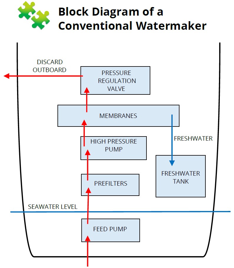
In this section, we will follow the desalination cycle in the same order in which water moves through a conventional reverse osmosis system during normal operation.
🌊 Following the Water Through the System
The process begins at the seawater intake, where raw seawater first enters the boat. The water then passes through the sea strainer and reaches the feed pump, which supplies a steady flow to the prefilters.
The prefilters remove suspended particles before the seawater enters the high-pressure section. The high-pressure pump then raises the pressure to the level required by the reverse osmosis membrane.
Inside the membrane vessel, the seawater is divided into two different streams:
- Product water or permeate: The freshwater that passes through the membrane and is sent toward the freshwater tank after its quality has been checked.
- Brine or concentrate: The remaining seawater, now containing a higher concentration of salts, which passes through the pressure-regulating valve and is discharged overboard.
🔍 What We Will Explain for Each Component
Each stage of the system will be covered individually, with attention to both function and practical installation.
- Purpose: What the component does and why it is required.
- Position in the system: Where it belongs in the hydraulic sequence.
- Installation: How and where it should normally be mounted onboard.
- Connections: Which hoses, fittings, electrical supplies or controls are required.
- Maintenance: What should be inspected, cleaned or replaced.
- Common problems: What can reduce performance or cause unreliable operation.
⚙️ A System Designed Around Balance
A reliable watermaker depends on correctly matched components rather than on any single oversized or expensive part. Feed flow, pump capacity, membrane size, operating pressure and freshwater production must all remain in balance.
A larger membrane, for example, will not automatically produce more water if the high-pressure pump cannot supply the required flow. In the same way, increasing pressure cannot compensate indefinitely for poor prefiltration, low feed flow or an unsuitable membrane configuration.
🛠️ Guidance for DIY Builders
Throughout this chapter, we refer to Blue Gold components and configurations because they have been selected for marine use and are available as individual parts, kits or complete systems.
However, the hydraulic principles described here are not limited to Blue Gold products. The same guidance remains useful when building, repairing or upgrading a system with other suitable marine reverse osmosis components.
📚 Components Covered in This Chapter
- Seawater intake and through-hull fitting
- Sea strainer
- Feed pump
- Prefilter housings and cartridges
- High-pressure pump and motor
- Pressure gauge and safety devices
- Reverse osmosis membrane and pressure vessel
- Pressure-regulating valve
- Brine discharge
- Product-water outlet and flow measurement
- Salinity monitoring and freshwater diversion
- Freshwater flushing and preservation circuit
We will now begin with the seawater intake: the first gateway between the sea and the watermaker.
Every watermaker begins at one essential point: bringing seawater onboard in a safe, reliable and efficient way. The through-hull inlet, seacock and sea strainer form the first stage of the desalination cycle.
Even the most advanced watermaker will not operate correctly if the intake does not provide a steady, clean and air-free supply of seawater.
🌊 1. What the Seawater Intake Does
The seawater intake supplies raw seawater to the feed pump and the rest of the system. It must remain reliable under different operating conditions, including when the boat is stationary, sailing, motoring or moving through disturbed water.
The intake should be:
- Securely mounted below the waterline: This ensures that the inlet remains submerged during normal operation.
- Capable of supplying a steady flow: The feed pump must receive enough seawater without restrictions or interruptions.
- Protected from debris and marine growth: A sea strainer prevents larger particles from entering the pump and filter system.
- Resistant to corrosion: Materials must be suitable for continuous exposure to seawater.
- Mechanically strong: The through-hull fitting, seacock and hose connections must withstand vibration and hull movement.
📐 2. Recommended Through-Hull Size
For many conventional BlueGold installations, we recommend a dedicated ¾-inch through-hull fitting combined with a 20 mm hose connection.
The intake should be installed as low as practical on the hull, where it can maintain a stable water column and remain submerged under normal sailing and motoring conditions.
🚫 3. Use a Dedicated Intake
Whenever possible, the watermaker should have its own dedicated seawater intake rather than sharing one with another onboard system.
Avoid sharing the intake with equipment such as:
- Marine toilets
- Engine cooling circuits
- Air-conditioning systems
- Deck-wash pumps
- Other pumps with intermittent or high flow demand
➡️ 4. Intake Grille Orientation
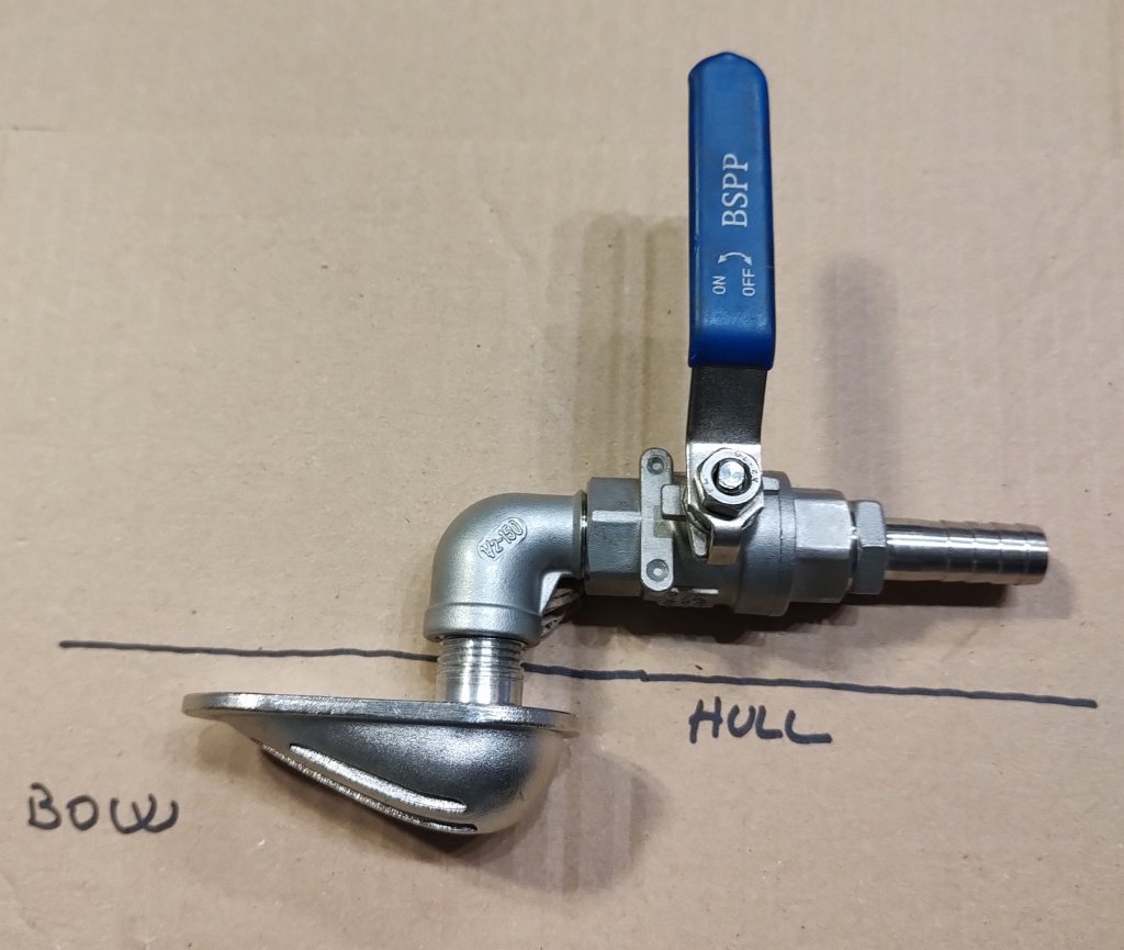
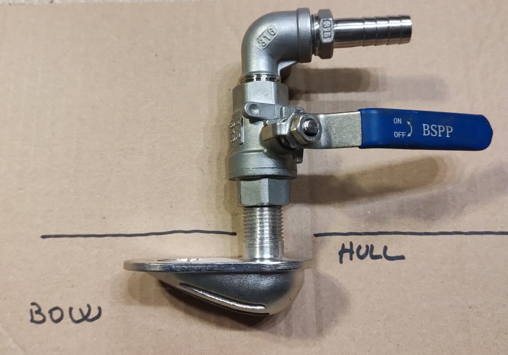
When a scoop or grille-type through-hull fitting is used, it should normally face forward, toward the bow.
While the boat is moving, this orientation creates a small positive pressure at the inlet and helps supply seawater to the system.
🔎 5. Using an Existing Spare Intake
An existing spare through-hull may be suitable, provided that it is correctly positioned, adequately sized and not shared with another system.
Before using it, verify:
- The internal diameter of the through-hull and hose connection
- Its distance below the normal waterline
- The absence of restrictions, sharp bends or undersized valves
- The condition of the fitting and seacock
- That the inlet remains submerged when the boat heels or pitches
🧹 6. Sea Strainer Access
The sea strainer should be installed where its transparent bowl or filter basket can be inspected and removed easily.
Leave enough clearance below and around the strainer to allow routine cleaning without dismantling nearby components.
🔩 7. Materials and Corrosion Resistance
All fittings exposed to seawater must be made from suitable marine materials.
BlueGold-approved intake assemblies may use:
- AISI 316L stainless steel: Suitable for high-quality seawater fittings when correctly installed and electrically isolated where required.
- Marine-grade polymers: Lightweight, corrosion-resistant and widely used for strainers and selected through-hull components.
- Suitable bronze or approved marine alloys: Commonly used for seacocks and through-hull fittings.
✅ 8. Quick Installation Checklist
| Check | Recommended condition |
|---|---|
| Intake position | Below the waterline and continuously submerged |
| Through-hull size | Normally ¾ inch for the intended installation |
| Hose connection | Approximately 20 mm where specified |
| Shared with other systems | No, preferably dedicated to the watermaker |
| Grille direction | Facing forward when a scoop-type inlet is used |
| Sea strainer access | Easy to inspect, open and clean |
| Materials | Suitable for seawater and corrosion-resistant |
A correctly sized, properly positioned and easily serviceable intake provides the stable water supply required by every component that follows.
The feed pump, also called the booster pump or low-pressure pump, is one of the most important components in a marine watermaker. Its purpose is to deliver a steady, air-free and adequately pressurised flow of seawater through the prefilters and toward the high-pressure section.
A watermaker cannot operate reliably if the high-pressure pump is starved of water. Insufficient feed flow, air entering the suction line or excessive restriction before the high-pressure pump can cause unstable pressure, reduced freshwater production, cavitation, noise and premature wear.
🌊 1. What the Feed Pump Does
The feed pump draws or receives seawater from the through-hull intake/strainer and pushes it through the hoses and prefilter cartridges. It must overcome the pressure losses created by these components while still delivering sufficient flow to the high-pressure pump.
A correctly selected feed pump should provide:
- Continuous seawater flow: The high-pressure pump should never be allowed to run without an adequate supply of water.
- Positive inlet pressure: A small positive pressure at the high-pressure pump inlet helps prevent cavitation and unstable operation.
- Enough reserve capacity: The pump should compensate for normal filter loading and reasonable hose losses.
- Stable operation: Flow should remain consistent throughout the desalination cycle.
⚙️ 2. Two Valid Feed-Pump Solutions
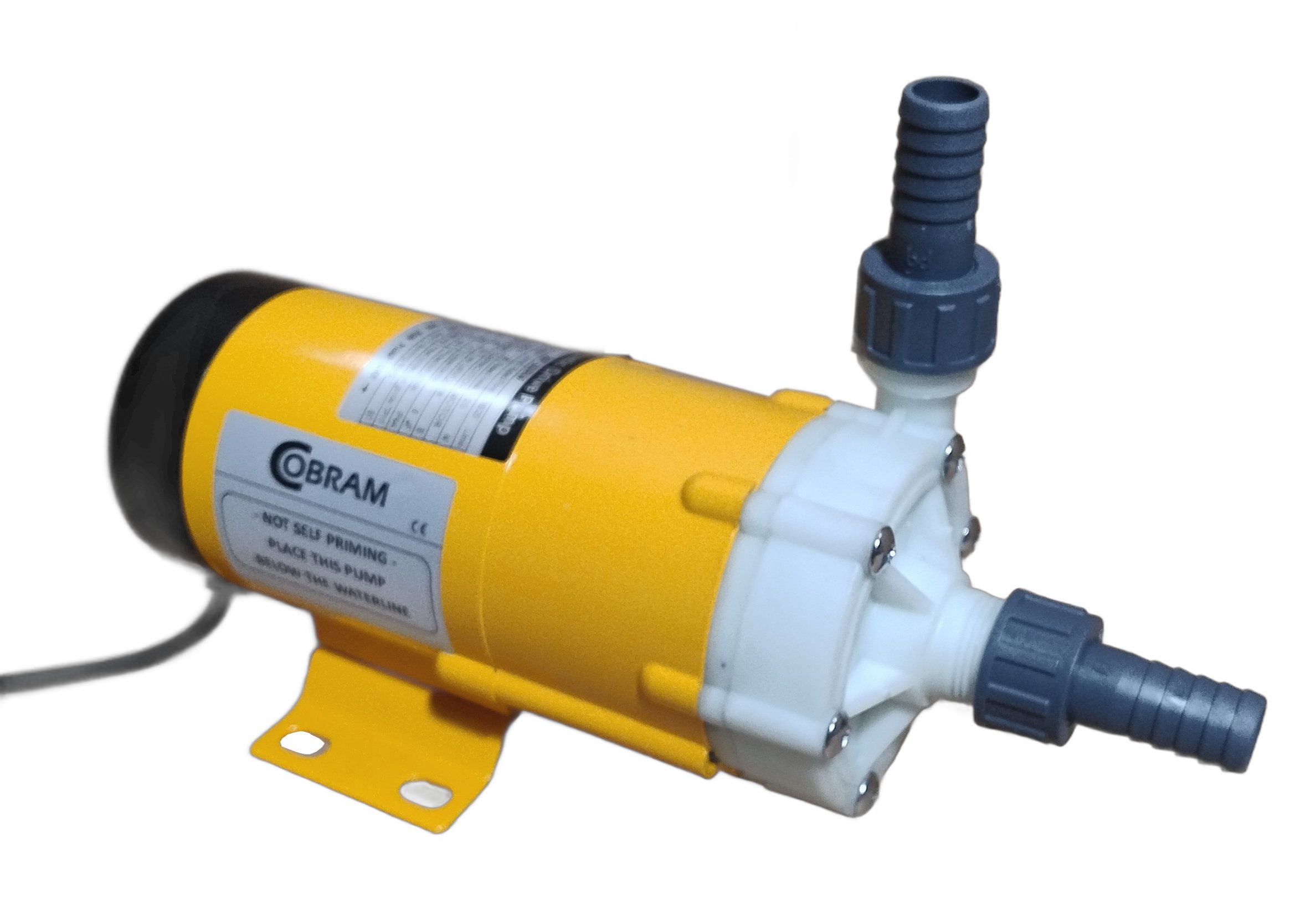
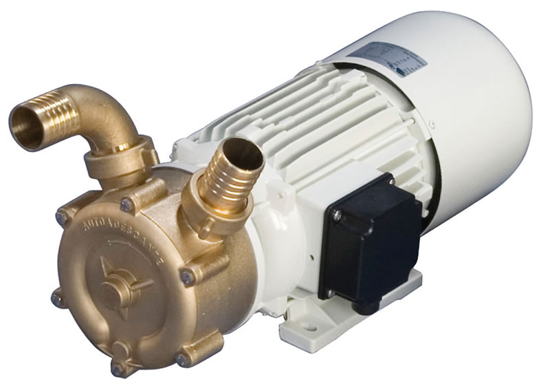
BlueGold supports two different feed-pump concepts: magnetic-drive centrifugal pumps and self-priming marine-bronze pumps. Neither solution is universally better. The correct choice depends on installation height, available space, electrical consumption and the operating requirements of the watermaker.
🧲 3. Magnetic-Drive Centrifugal Feed Pumps
Magnetic-drive pumps transmit motor power to the impeller through a magnetic coupling. There is no conventional rotating shaft passing through the pump housing and therefore no shaft seal between the seawater circuit and the motor.
These pumps are particularly suitable when the installation allows the pump to be positioned below the waterline, close to the seawater intake.
⭐ Main Characteristics
- Very low electrical consumption: Depending on the model, consumption may remain below approximately 50 W.
- No conventional shaft seal: This removes a common leakage and maintenance point.
- Quiet operation: Magnetic-drive pumps are generally smooth and produce little vibration.
- Compact size: Their small footprint is useful in machinery lockers and modular installations.
- Low routine maintenance: There are no brushes, belts or shaft couplings in the pump head.
- Good energy efficiency: Particularly useful on battery- and solar-supported boats.
📐 Installation Requirements
- Install the pump below the waterline whenever possible.
- Position it close to the through-hull and sea strainer.
- Keep the suction hose short, straight and free from high loops.
- Avoid restrictions, undersized valves and unnecessary fittings.
- Ensure the pump remains flooded before startup.
- Provide easy access for hose inspection and electrical connections.
⚓ 4. Self-Priming Marine-Bronze Feed Pumps
A self-priming marine-bronze pump is an alternative for installations where it is difficult or impractical to position the feed pump below the waterline.
This can be particularly useful on catamarans, shallow hulls or boats where the available machinery space is located above the normal seawater level.
The BlueGold C.E.M. 020 is a self-priming side-channel pump manufactured with a bronze pump body, bronze impeller and corrosion-resistant marine materials. It must be filled with water during initial commissioning so that the priming cycle can begin correctly.
⭐ Main Characteristics
- Self-priming operation: Once initially filled and correctly installed, the pump can evacuate air from the suction line and restore seawater flow.
- Flexible installation position: It may be installed above the waterline when necessary, within the permitted suction-height limits.
- Marine-bronze construction: Suitable materials are used for seawater service.
- Strong suction capability: Useful where the intake and pump cannot be positioned at the same level.
- Robust mechanical design: Well suited to demanding marine installations.
- Continuous-duty capability: Appropriate for the sustained operating periods required by a watermaker.
⚡ Electrical Consumption
The greater suction capability and more robust mechanical construction require more electrical power than a small magnetic-drive pump.
The BlueGold C.E.M. 020 installation should be planned for approximately 200 W, depending on the exact voltage and motor configuration.
🪣 Initial Priming
Self-priming does not mean that the pump should be started completely dry. During initial commissioning, the pump body and suction circuit must be filled with water according to the installation instructions.
- Fill the pump body before the first startup.
- Check that the suction line and fittings are airtight.
- Open the seacock fully.
- Verify that the strainer bowl and suction hose contain water.
- Do not allow prolonged dry running.
⚖️ 5. Magnetic-Drive or Self-Priming Bronze?
| Feature | Magnetic-Drive Pump | Self-Priming Bronze Pump |
|---|---|---|
| Typical installation | Below the waterline | Below or, when necessary, above the waterline |
| Priming behaviour | Normally requires flooded suction | Self-priming after initial filling |
| Approximate consumption | Usually below 50 W | Approximately 200 W |
| Noise and vibration | Very low | Moderate mechanical pump noise |
| Suction flexibility | Limited | High |
| Construction | Typically technical polymer pump head | Marine-bronze pump body and impeller |
| Maintenance points | No conventional shaft seal | Includes mechanical seal and conventional pump components |
| Best priority | Minimum energy consumption | Installation flexibility and self-priming capability |
📏 6. Correct Flow and Pressure Matter More Than Pump Type
Regardless of the pump technology, the feed pump must supply the flow required by the high-pressure pump and membrane configuration.
An undersized feed pump can cause:
- Low inlet pressure at the high-pressure pump
- Cavitation and irregular pump noise
- Unstable operating pressure
- Reduced freshwater production
- Premature high-pressure pump wear
- Difficulty compensating for partially loaded prefilters
An unnecessarily oversized pump can increase electrical consumption, noise and bypass requirements without improving membrane performance.
🧱 7. Prefilters and Suction Restrictions
The feed pump must overcome the resistance created by the sea strainer, hoses, valves and filter cartridges.
As filter cartridges collect sediment, their pressure loss increases. The feed-pump selection should therefore include enough reserve to maintain correct flow throughout the normal service interval.
- Use correctly sized suction hoses.
- Avoid narrow fittings and unnecessary reducers.
- Keep suction runs as short as possible.
- Use smooth bends instead of multiple tight elbows.
- Inspect and replace clogged cartridges promptly.
- Check for air leaks on the suction side.
🔧 8. Installation and Maintenance Checklist
| Check | Recommended condition |
|---|---|
| Pump capacity | Matched to high-pressure pump flow and membrane layout |
| Suction hose | Short, airtight and correctly sized |
| Installation height | Compatible with the selected pump technology |
| Prefilters | Clean and not excessively restrictive |
| Electrical supply | Correct voltage, cable size, fuse and polarity |
| Priming | Completed before initial operation |
| Air leaks | None on the suction side |
| Service access | Pump, strainer and filters remain easy to inspect |
🧭 9. Which Solution Should You Choose?
- Choose a magnetic-drive pump when it can be installed below the waterline and minimum electrical consumption, quiet operation and simplicity are the main priorities.
- Choose a self-priming bronze pump when installation geometry makes flooded suction difficult, when the pump must be positioned above the waterline or when stronger suction capability is required.
The correct choice depends on the boat’s layout, the available electrical power and the hydraulic requirements of the watermaker. What matters most is delivering a stable, clean and air-free flow to the high-pressure pump at all times.
Freshwater flushing is one of the simplest and most effective ways to protect a marine watermaker between operating cycles. After producing water, the flushing circuit replaces the concentrated seawater remaining inside the prefilters, pumps, membrane vessels and hydraulic lines with clean freshwater from the boat’s tank.
The BlueGold Easy Flushing System performs this operation through an electric solenoid valve controlled by a simple switch. It can be integrated into new installations or added to many existing marine watermakers, regardless of brand.
💧 1. Why Freshwater Flushing Matters
When a watermaker stops, seawater remains trapped inside much of the hydraulic circuit. As this water sits, it can contribute to:
- Salt crystallisation inside valves, pumps and fittings.
- Biological growth in hoses, filters and membrane vessels.
- Sticking check valves and pressure-regulating components.
- Corrosion of metallic pump and valve parts.
- Unpleasant odours after periods of inactivity.
- More frequent membrane cleaning and maintenance.
A freshwater flush greatly reduces the salt concentration and biological load remaining inside the system. It does not replace proper preservation when the watermaker will remain unused for a long period, but it is ideal for routine shutdowns between normal operating cycles.
⚙️ 2. How the Easy Flushing System Works
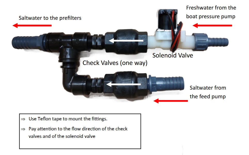
The flushing line connects the boat’s pressurised freshwater supply to the low-pressure side of the watermaker. When the electric solenoid valve is opened, freshwater enters the feed circuit and follows essentially the same route normally used by seawater.
Freshwater tank or pressure-water system → flushing solenoid valve → feed pump and prefilters → high-pressure pump or energy-recovery unit → membrane vessels → brine discharge.
The two check valves automatically control the direction of flow:
- The seawater-intake check valve prevents pressurised flushing water from flowing backwards and escaping through the intake through-hull.
- The freshwater-line check valve prevents seawater from flowing backwards into the boat’s freshwater plumbing.
This allows seawater and freshwater to share the downstream feed circuit while keeping the two sources hydraulically separated.
🔄 3. The Two Check Valves Are Essential
Although the flushing circuit appears simple, correct check-valve selection is critical. The valves must operate reliably with seawater, create very little flow restriction and open at extremely low pressure.
BlueGold uses check valves manufactured from saltwater-compatible engineering polymer, with internal metallic parts and springs made from AISI 316L stainless steel. In versions specified with PTFE components, the wetted sealing parts are also selected for chemical and saltwater resistance.
Intake-Side Check Valve
The intake-side valve allows seawater to travel from the through-hull toward the feed pump during normal watermaker operation.
During freshwater flushing, it closes automatically and prevents the freshwater supply from being discharged backwards through the hull fitting.
Freshwater-Side Check Valve
The second valve permits freshwater to enter the watermaker when the flushing solenoid is activated, but prevents seawater from moving backwards toward the freshwater tank and domestic plumbing.
🚫 4. Why Domestic Brass Check Valves Must Be Avoided
Ordinary domestic plumbing check valves may look suitable, but they are normally designed for pressurised freshwater systems rather than low-pressure seawater suction circuits.
They can create several problems:
- Excessively stiff spring: The small hydrostatic pressure available at the seawater intake may not be sufficient to open the valve fully.
- Restricted feed flow: A partially opened valve can starve the feed pump and high-pressure pump.
- Priming difficulties: The intake line may fail to flood correctly, particularly when using a small magnetic-drive feed pump.
- Unsuitable brass composition: Domestic brass may deteriorate through dezincification or corrosion in seawater.
- Non-marine spring material: Internal springs may corrode, weaken or seize.
- High pressure loss: A valve designed for mains-water pressure can impose a significant restriction at the low pressures used on the feed side of a watermaker.
The material, internal geometry, spring strength, opening pressure and suitability for seawater are all essential.
🌊 5. Why Low Cracking Pressure Matters
The pressure required to begin opening a check valve is often called its cracking pressure.
In a domestic pressurised-water system, a moderately strong spring may not be a problem because several bars of pressure are available. At a boat’s seawater intake, however, the available natural head may only be a small fraction of one bar.
A check valve with excessive cracking pressure can therefore behave almost like a closed valve, even though it appears mechanically correct.
This is particularly important with compact magnetic-drive pumps, which move water efficiently but are normally not self-priming and have limited suction capability.
🔌 6. Electric Flushing Operation
The electric version uses a 12 V or 24 V solenoid valve connected to a switch or watermaker controller.
A typical manual electric-flush sequence is:
- Finish the normal freshwater-production cycle.
- Reduce high pressure completely and stop the high-pressure pump.
- Leave the low-pressure flushing path open according to the watermaker instructions.
- Activate the flushing switch.
- The solenoid valve opens and freshwater enters the feed circuit.
- The intake check valve closes, preventing water from escaping overboard through the through-hull.
- Freshwater flows through the watermaker and exits through the normal brine discharge.
- After the specified flushing time, switch the solenoid valve off.
🕹️ 7. Fully Manual Alternative: A Three-Way Valve
An electric solenoid valve is convenient, but it is not compulsory. Builders who prefer a completely manual and electrically independent system can use a suitable three-way valve to select between seawater and freshwater.
The three-way valve has:
- One inlet connected to the seawater intake.
- One inlet connected to the freshwater flushing supply.
- One common outlet connected to the feed pump and watermaker.
In the normal position, the valve connects the watermaker to the seawater intake. For flushing, it is turned manually to connect the freshwater supply instead.
The manual valve must be suitable for potable water and seawater, have an adequate internal bore and produce minimal restriction in the seawater-feed position.
⚖️ 8. Electric System or Manual Three-Way Valve?
| Feature | Electric Solenoid System | Manual Three-Way Valve |
|---|---|---|
| Operation | Activated by switch or controller | Operated manually |
| Electrical supply | 12 V or 24 V required | Not required |
| Automation | Can be integrated into an automatic sequence | Fully dependent on the operator |
| Convenience | Very high | Simple but requires physical access |
| Number of moving/electrical parts | Includes solenoid and wiring | Single manually operated valve |
| Best suited for | Semi-automatic and automatic systems | Simple manual DIY systems |
Both arrangements can work reliably. The choice depends on the desired level of automation, available electrical control and the owner’s preferred operating method.
📐 9. Installation Guidelines
- Install both check valves in the correct flow direction.
- Follow the arrows moulded or marked on the valve bodies.
- Keep hoses short and avoid unnecessary restrictions.
- Use hose and fittings with an internal diameter appropriate for the feed flow.
- Mount the solenoid valve in a dry, accessible position.
- Protect electrical connections from moisture.
- Make the valves accessible for inspection and replacement.
- Use only components compatible with seawater and potable freshwater.
- Do not install domestic spring-loaded brass check valves.
- Confirm that the freshwater system can provide the required flushing flow.
🔍 10. Commissioning and Functional Test
Before relying on the system, test both operating modes carefully.
Normal Seawater Operation
- Confirm that seawater floods the intake line freely.
- Check that the intake check valve opens without excessive restriction.
- Verify stable feed-pump flow.
- Confirm that no seawater enters the freshwater flushing line.
Freshwater Flushing Operation
- Activate the solenoid or turn the manual three-way valve.
- Confirm that freshwater flows toward the watermaker.
- Check that no freshwater exits through the intake through-hull.
- Verify flow at the normal brine discharge.
- Inspect every connection for leakage.
🧰 11. Maintenance
The flushing system requires little maintenance, but its operation should be checked periodically.
- Inspect check valves for debris or salt deposits.
- Verify that the valves open freely at low pressure.
- Check that the solenoid valve opens and closes completely.
- Inspect electrical connectors for moisture or corrosion.
- Check hoses for hardening, cracking or leakage.
- Confirm that the freshwater side remains isolated during seawater operation.
- Test the flushing cycle after prolonged inactivity.
✅ 12. Quick Selection Checklist
| Component | Required characteristic |
|---|---|
| Intake check valve | Saltwater-compatible, full-flow and very low cracking pressure |
| Freshwater check valve | Suitable for potable water and resistant to reverse seawater flow |
| Internal spring | AISI 316L stainless steel with light opening force |
| Valve body | Saltwater-compatible engineering polymer or specified PTFE construction |
| Electric valve | Correct 12 V or 24 V version and compatible wetted materials |
| Manual alternative | Full-bore, low-restriction three-way valve suitable for both water sources |
| Domestic brass check valve | Do not use |
Low-resistance marine check valves keep the seawater feed circuit free-flowing, isolate the freshwater supply and ensure that flushing water travels through the watermaker instead of escaping through the intake. The electric version adds push-button convenience, while a suitable three-way valve provides an equally valid fully manual solution.
Pre-filtration is one of the most important parts of a marine watermaker. Before seawater reaches the high-pressure pump, Clark Pump or reverse osmosis membrane, suspended particles, sand, silt and biological material must be removed as effectively as possible.
A correctly designed prefilter system protects the most valuable components of the installation, helps maintain stable flow and reduces membrane fouling. Poor or neglected filtration can affect the entire watermaker, even when the seawater appears visually clean.
🌊 1. Why Pre-Filtration Is Essential
Seawater contains more than visible sand or debris. It may also contain fine sediment, plankton, organic material, algae and microscopic marine growth.
Without effective pre-filtration, these contaminants can:
- Restrict flow to the high-pressure pump or Clark Pump.
- Cause unstable pressure and reduced freshwater production.
- Increase the risk of cavitation at the high-pressure pump.
- Deposit inside valves, hoses and small hydraulic passages.
- Promote biological fouling of the membrane.
- Increase cleaning frequency and operating costs.
- Trigger low-flow or low-pressure alarms in automated systems.
⚙️ 2. Recommended Filter Configurations
The appropriate filtration arrangement depends mainly on the seawater flow required by the high-pressure pump and on the expected water quality.
Systems up to approximately 5 litres per minute
For small systems with relatively low feed flow, a single 5-micron melt-blown cartridge is often sufficient, provided that the seawater intake includes a suitable sea strainer and the operating area is not unusually dirty.
Systems above approximately 5 litres per minute
For larger systems, BlueGold normally recommends a two-stage arrangement:
- 20-micron cartridge: Captures larger particles and protects the second filter.
- 5-micron cartridge: Provides finer filtration before the high-pressure section.
🧵 3. Melt-Blown or String-Wound Cartridges?
For marine watermaker pre-filtration, BlueGold generally recommends melt-blown polypropylene cartridges rather than traditional string-wound cartridges.
Advantages of Melt-Blown Cartridges
- Graded-density construction: Larger particles are captured in the outer layers while finer material is retained deeper inside the cartridge.
- High dirt-holding capacity: Contamination is distributed through the depth of the filter rather than being concentrated only on the surface.
- More uniform filtration: The continuous polypropylene structure offers consistent filtration without gaps between wound fibres.
- Good flow behaviour: A correctly sized melt-blown cartridge normally maintains usable flow as it gradually loads.
- No loose winding fibres: There are no strings or threads that can unravel or migrate downstream.
- Low cost and easy replacement: Standard DOE cartridges are widely available and simple to keep onboard as spares.
Limitations of String-Wound Cartridges
String-wound cartridges can work in many industrial applications, but their performance depends strongly on manufacturing quality and winding consistency.
Potential disadvantages include:
- Uneven flow paths between the wound fibres.
- Possible channel formation as the cartridge loads.
- Lower consistency between inexpensive cartridges.
- Possible release of small fibres or winding material.
- Less predictable filtration when exposed to changing flow and pressure.

🧽 4. Why Not Use Washable Filters as the Main Prefilter?
Washable mesh or screen filters can be useful as coarse strainers, but they should not normally replace disposable fine-filter cartridges immediately before the high-pressure section.
Most washable filters are designed to stop relatively large debris. They may not provide the consistent 5-micron filtration required to protect pumps and membranes from fine sediment and biological material.
Common Limitations
- Coarser filtration: Many washable elements stop shells, leaves or larger particles but allow fine sediment to pass through.
- Uncertain performance after cleaning: The element may appear clean while fine material remains trapped inside the mesh.
- Risk of damage: Aggressive brushing or pressure washing can deform or enlarge the filtering surface.
- Biological contamination: Biofilm can remain on the element even after a visual rinse.
- No depth filtration: A screen normally captures particles mainly on its surface rather than throughout the depth of the cartridge.
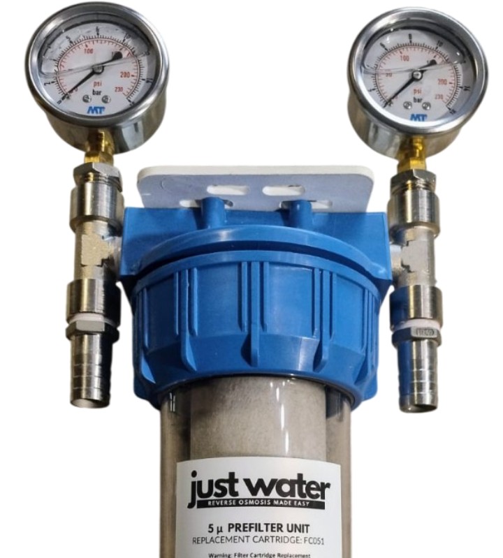
📏 5. Monitoring Filter Condition with Pressure Gauges
A useful prefilter assembly may include one gauge before the cartridges and another after them. Comparing the two readings indicates how much resistance the cartridges are creating.
- Upstream pressure: Pressure entering the prefilter assembly.
- Downstream pressure: Pressure available after the cartridges and before the high-pressure pump.
The difference between these values is the filter pressure differential.
Typical Interpretation
- Approximately 0.1–0.3 bar: Often normal for clean or lightly loaded cartridges, depending on flow and installation.
- A steadily increasing differential: Indicates that the cartridges are collecting contamination.
- Approximately 0.5 bar or more: The cartridges should normally be inspected and replaced.
- Very low downstream pressure accompanied by poor flow: May indicate heavily blocked filters, an intake restriction or an inadequate feed supply.
🧲 6. Why Small Magnetic Pumps May Show Almost No Gauge Pressure
Compact magnetic-drive feed pumps are designed primarily to move water, not to generate high static pressure. In a small, low-resistance watermaker circuit, the gauges may therefore indicate only a few tenths of a bar or appear to remain close to zero.
This does not necessarily mean that the pump is not working correctly.
Low readings are common when:
- The feed pump has a low-pressure, high-flow characteristic.
- The suction and discharge hoses are short and correctly sized.
- The filter cartridges are clean.
- The high-pressure pump accepts the supplied flow without creating significant backpressure.
- The gauge range is too large to display small pressure changes clearly.
The important operating condition is that the high-pressure pump receives a continuous, air-free supply of seawater with enough positive flow to prevent cavitation.
🔍 7. Pressure Is Not the Same as Flow
Pressure and flow describe two different aspects of the feed circuit. A pump can provide adequate flow while producing very little measurable pressure if the circuit has low resistance.
Conversely, a blocked filter can create pressure before the restriction while providing insufficient flow after it.
When diagnosing the system, consider together:
- Pressure before the filters.
- Pressure after the filters.
- Feed-water flow.
- High-pressure pump noise and stability.
- Freshwater production.
- The age and visible condition of the cartridges.
⚠️ 8. What Happens When Prefilters Are Neglected?
Clogged or biologically contaminated cartridges increase resistance and progressively reduce the flow available to the rest of the system.
Possible consequences include:
- Starvation of the conventional high-pressure pump or Clark Pump.
- Cavitation, irregular operation and pump overheating.
- Unstable high-pressure readings.
- Reduced freshwater output.
- Higher electrical consumption as pumps operate under unsuitable conditions.
- Membrane fouling caused by fine solids or organic material.
- Low-flow or low-pressure shutdowns in automated systems.
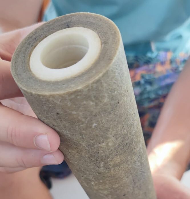
🧫 9. Biological Growth and Filter Hygiene
Seawater trapped inside filter housings can support bacterial and biological growth, particularly in warm climates.
Freshwater flushing reduces salt concentration and biological activity in the downstream watermaker circuit, but the intake and prefilter arrangement should still be inspected regularly.
- Do not leave heavily contaminated cartridges installed during long periods of inactivity.
- Replace cartridges that smell unpleasant or show signs of biological growth.
- Clean filter bowls before installing new cartridges.
- Do not handle clean cartridges with dirty or oily hands.
- Keep replacement cartridges dry and sealed until required.
📦 10. Standard 10-Inch or Extended 20-Inch Filters?
BlueGold systems normally use standard 10-inch DOE melt-blown cartridges. They provide a good balance between compact dimensions, availability, filtration capacity and ease of replacement.
10-Inch Cartridges
- Compact and easy to install in confined spaces.
- Widely available from marine and industrial suppliers.
- Easy to carry onboard as spares.
- Suitable for most small and medium watermakers.
20-Inch Cartridges
- Greater filtering surface.
- Higher dirt-holding capacity.
- Lower pressure drop at the same flow rate.
- Longer service intervals.
- Particularly useful for high-flow systems or long-distance cruising.
🔧 11. Cartridge Replacement and Housing Maintenance
Replace cartridges when the pressure differential becomes excessive, when flow decreases noticeably or when contamination is suspected.
Recommended Procedure
- Stop the watermaker and close the seawater intake if required.
- Release any pressure from the filter housing.
- Unscrew the bowl using the correct housing wrench.
- Remove and discard the used cartridge.
- Clean the inside of the bowl with fresh water.
- Inspect the housing O-ring for dirt, flattening or damage.
- Apply a very light film of silicone grease to the O-ring.
- Install the new cartridge and refit the bowl.
- Prime the circuit and inspect carefully for leaks.
📋 12. Quick Pre-Filter Selection Guide
| System condition | Suggested arrangement |
|---|---|
| Small system, up to approximately 5 L/min | Single 5-micron melt-blown cartridge |
| Flow above approximately 5 L/min | 20-micron cartridge followed by 5-micron cartridge |
| Dirty or biologically active water | Two-stage filtration with frequent monitoring and replacement |
| High-flow installation | Consider 20-inch housings to reduce restriction |
| Compact low-power system | 10-inch housings with low-restriction melt-blown cartridges |
| Washable mesh element | Use as coarse upstream protection, not as the final 5-micron stage |
✅ 13. Pre-Filter Maintenance Checklist
- Record clean-filter pressure readings during commissioning.
- Monitor the pressure difference before and after the cartridges.
- Do not wait for complete blockage before replacing the filters.
- Inspect the sea strainer and intake at the same time.
- Keep several replacement cartridges onboard.
- Store spare filters in sealed, dry packaging.
- Leave enough clearance below each housing for easy servicing.
- Lightly lubricate housing O-rings with silicone grease.
- Check for leaks and trapped air after every cartridge change.
The correct cartridges, adequate filter area and regular monitoring ensure that the high-pressure pump receives a clean, stable and unrestricted seawater supply—one of the basic conditions for reliable freshwater production.
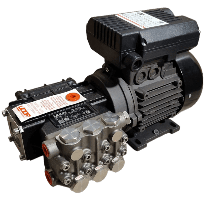
The high-pressure pump is the heart of every conventional marine watermaker. Its role is to deliver a controlled flow of seawater at the pressure required by the reverse osmosis membrane to separate freshwater from dissolved salts.
Unlike the feed pump, which supplies the system at low pressure, the high-pressure pump operates in the region normally required for seawater reverse osmosis. Correct pump selection, motor sizing, feed-water supply, pressure regulation and maintenance are all essential for reliable operation.
💧 1. What the High-Pressure Pump Does
The high-pressure pump receives filtered seawater from the feed side and moves a fixed volume of water through the reverse osmosis membrane circuit.
In a conventional system, the pump provides the flow while the operating pressure develops when the concentrate stream is restricted by the pressure-regulating valve.
The high-pressure pump must provide enough flow for the selected membrane configuration while remaining within its rated speed, pressure, temperature and power limits.
📏 2. Normal Seawater RO Operating Pressure
Marine seawater reverse osmosis systems commonly operate at approximately 55–60 bar, although the exact pressure depends on several factors:
- Seawater salinity
- Water temperature
- Membrane size and number
- Desired freshwater production
- Membrane age and condition
- Feed-water flow
Cold or highly saline seawater may require a different operating pressure from warm, lower-salinity water. The objective is not to reach the highest possible pressure, but to obtain the required production while remaining within the limits of the membrane, pump, vessel and fittings.
🎛️ 3. How Pressure Is Regulated
The operating pressure is normally adjusted with a needle valve or purpose-designed pressure-regulating valve installed on the concentrate or brine outlet.
Closing the valve gradually increases resistance and therefore raises the pressure inside the membrane circuit. Opening it reduces pressure and allows more brine to flow overboard.
Never Adjust Pressure Abruptly
- Do not close the regulating valve suddenly.
- Do not start the motor against unnecessarily high residual pressure.
- Increase pressure gradually while observing the high-pressure gauge.
- Confirm that concentrate flow remains present.
- Never exceed the rated pressure of the pump, vessel, membrane or fittings.
🛡️ 4. Pressure Gauge and Safety Devices
Every conventional high-pressure system should include a clearly visible pressure gauge installed in a suitable position on the high-pressure circuit.
Depending on the design, the system should also include a pressure relief valve or another reliable means of preventing accidental overpressure.
Recommended Safety Elements
- High-pressure gauge with an appropriate range
- Pressure relief valve or equivalent protection
- Pressure-rated hoses and fittings
- Pressure vessel rated above the maximum operating pressure
- Securely mounted regulating valve
- Guarding around exposed rotating couplings
🔩 5. Stainless-Steel or Brass Pump Head?
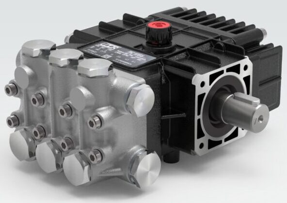
Marine high-pressure plunger pumps are commonly available with either an AISI 316L stainless-steel head or a suitable brass head.
Both solutions can be used successfully in a marine watermaker, but they offer different advantages in terms of cost, corrosion resistance and expected operating conditions.
AISI 316L Stainless-Steel Head
- Maximum corrosion resistance: Particularly suitable for intensive use and long-term exposure to seawater.
- Suitable for warm climates: High seawater temperatures can accelerate corrosion and biological activity.
- Long-term investment: Normally more expensive, but attractive for high-use or professional installations.
- Excellent mechanical durability: Well suited to demanding marine service.
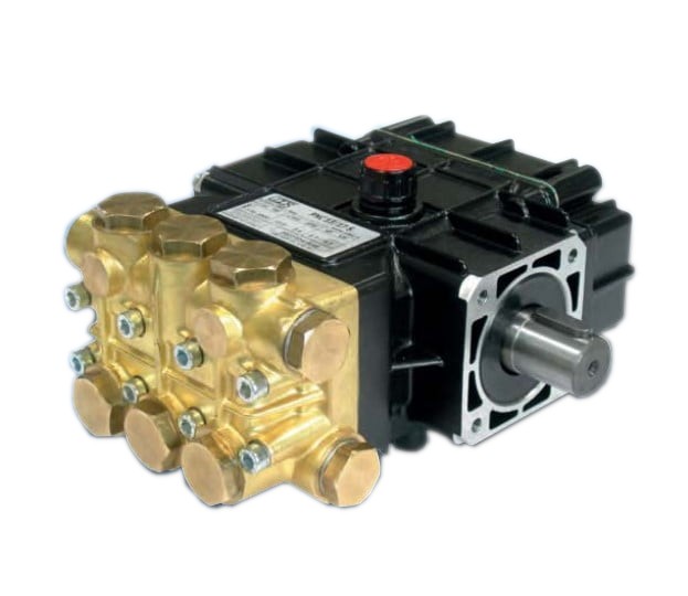
Brass Pump Head
- Lower initial cost: A practical option for many DIY and seasonal installations.
- Widely available: Replacement parts and service expertise are often easy to obtain.
- Suitable for seawater use: Provided that the pump is correctly selected, flushed and maintained.
- Good value: A reliable compromise when maximum corrosion resistance is not the primary requirement.
🌊 6. Correct Feed-Water Supply
A high-pressure plunger pump should not be expected to draw seawater through the complete intake and prefilter circuit by itself. It must receive a continuous and adequately supplied flow from the feed pump.
The inlet side should remain fully flooded and free from air during operation.
Insufficient Feed Supply Can Cause
- Cavitation
- Irregular mechanical noise
- Pressure fluctuations
- Reduced freshwater production
- Overheating
- Damage to seals and valves
- Premature pump wear
Small magnetic-drive feed pumps may show very little pressure on a gauge while still providing adequate flow. The condition of the high-pressure pump should therefore be assessed from feed flow, pressure stability, sound and overall system performance—not from feed pressure alone.
🚫 7. Never Run the Pump Dry
A high-pressure pump must never be allowed to operate without water, even for a short period.
The pumped water contributes to cooling and lubrication of the wet-end components. Dry running can rapidly damage:
- Plunger seals
- Valve seats
- O-rings
- Guides and internal surfaces
🔄 8. Pump Flow and Membrane Matching
Each high-pressure pump has a nominal flow rate, normally expressed in litres per minute. This flow must be matched to the membrane size and number of membrane vessels.
A pump that is too small may not provide enough cross-flow through the membrane. A pump that is unnecessarily large may increase power consumption, brine flow and pressure-control requirements without improving freshwater production proportionally.
Typical BlueGold Pump and Motor Combinations
| Pump flow | Approximate shaft power at 60 bar | Suggested motor rating |
|---|---|---|
| 4 L/min | 0.47 kW | 0.75 kW |
| 6 L/min | 0.69 kW | 0.75 kW |
| 8 L/min | 0.93 kW | 1.1 kW |
| 11 L/min | 1.27 kW | 1.5 kW |
| 13 L/min | 1.50 kW | 2.2 kW |
🧮 9. Calculating Required Mechanical Power
The theoretical hydraulic power required to move water at a given pressure and flow can be estimated using:
Power (kW) = Pressure (bar) × Flow (L/min) ÷ 600
Real pumps are not perfectly efficient. Mechanical and volumetric losses mean that the motor must supply more shaft power than the theoretical hydraulic value.
For practical preliminary sizing, BlueGold uses the more conservative empirical formula:
Power (kW) = Pressure (bar) × Flow (L/min) ÷ 520
Example: 6 L/min at 60 bar
The estimated mechanical power required is:
This is the approximate minimum mechanical power that must be available at the motor shaft. The selected motor should normally provide at least this value, with a reasonable safety margin.
⚡ 10. Mechanical Power vs. Electrical Consumption
The power printed on an electric motor nameplate normally refers to the mechanical output available at the shaft—not the electrical power drawn from the supply.
Because no motor is 100% efficient, the electrical input is always higher than the mechanical output.
Sources of Motor Losses
- Heat in the windings
- Bearing friction
- Magnetic losses
- Cooling fan losses
- Capacitor and power-factor losses in single-phase motors
A simple approximation of apparent electrical input can be obtained from the nameplate voltage and current:
Volts × Amps
For AC motors, actual real power also depends on power factor and efficiency, so nameplate data and manufacturer specifications should be used for final electrical design.
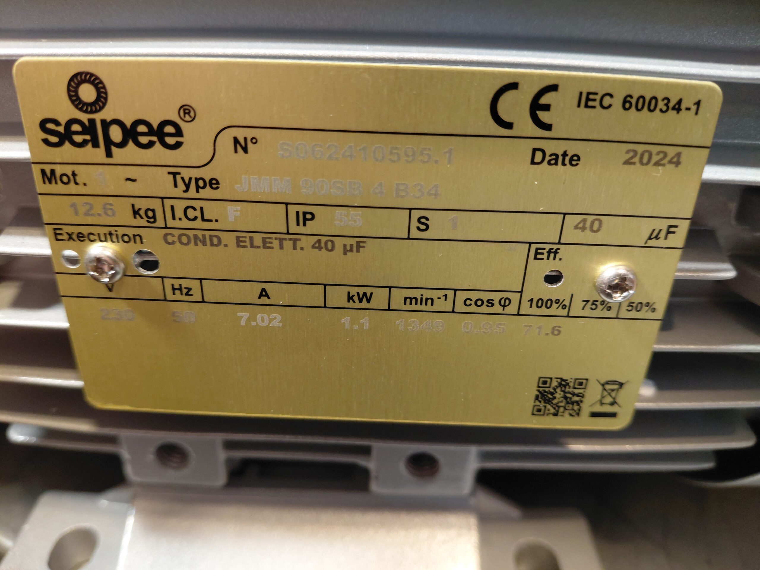
🏷️ 11. How to Read a Motor Nameplate
The motor nameplate contains the most important information required for power-system and installation planning.
Look For
- Rated voltage: For example 230 V AC, 400 V three-phase, 12 V DC or 24 V DC.
- Rated mechanical power: Expressed in kW or horsepower.
- Rated current: Important for cable, fuse, contactor and inverter sizing.
- Rotational speed: Often approximately 1450 rpm for a four-pole 50 Hz motor.
- Duty rating: Preferably S1 for continuous operation.
- Frequency: Normally 50 or 60 Hz.
- Protection rating: Indicates resistance to dust and water ingress.
- Insulation class: Relevant to operating temperature and durability.
🔌 12. AC, DC and Three-Phase Motors
Single-Phase AC Motors
- Common on boats using generators or inverters.
- Simple to integrate into a 230 V onboard system.
- Normally less efficient than comparable three-phase motors.
- Require correct capacitor and starting arrangements.
Three-Phase Motors
- Generally more efficient and mechanically smooth.
- Well suited to larger watermakers.
- Can be controlled by a suitable variable-frequency drive where the complete pump system permits it.
- Require appropriate electrical infrastructure.
DC Motors
- Can operate directly from 12 V or 24 V battery systems.
- High-current models require very large cables, fuses and switching devices.
- Voltage drop becomes particularly important at higher powers.
- Continuous-duty thermal performance must be verified carefully.
🔋 13. Inverter and Generator Sizing
The inverter or generator must support both the continuous running demand and the temporary startup load of the motor.
For example, an 1.1 kW single-phase motor may require approximately 1.3–1.4 kW of electrical input under full load, depending on efficiency and power factor.
The inverter should therefore not be selected at exactly the nominal motor rating.
Also consider the other electrical loads that may be running at the same time, such as:
- Feed pump
- Control panel
- Freshwater flushing pump
- Battery charger
- Refrigeration
- Navigation electronics
🧲 14. Start and Run Capacitors
BlueGold single-phase motors may use a dual-capacitor system consisting of a start capacitor and a run capacitor.
Start Capacitor
The start capacitor provides additional starting torque during the first seconds of operation. It is disconnected automatically after the motor reaches operating speed.
Run Capacitor
The run capacitor remains active during operation and helps support:
- Stable motor performance
- Improved power factor
- Reduced vibration
- Smoother operation
- Lower winding stress
🔄 15. Speed, Rotation and Frequency
Positive-displacement plunger pumps are designed to operate within a specified speed range.
Pump flow is approximately proportional to rotational speed. Increasing speed increases flow, power demand and mechanical stress.
Important Checks
- Use the rotational speed specified for the pump.
- Verify the motor frequency: 50 Hz and 60 Hz motors may run at different speeds.
- Confirm the correct direction of rotation before prolonged operation.
- Do not exceed the pump’s maximum rated speed.
- Do not use a variable-frequency drive without checking pump lubrication, minimum speed and cooling requirements.
🔗 16. Pump and Motor Coupling
The motor and pump must be mounted on a rigid base and connected with a correctly aligned coupling.
Misalignment can cause vibration, bearing wear, coupling damage and premature seal failure.
Installation Guidelines
- Use a suitable flexible coupling.
- Align pump and motor shafts carefully.
- Do not force the shafts into alignment by tightening mounting bolts.
- Mount the assembly on a rigid frame.
- Use vibration-damping mounts where appropriate.
- Protect exposed rotating components with a guard.
- Check mounting bolts after the first operating hours.
📐 17. Installation Position
The high-pressure pump may normally be installed above or below the waterline, provided that the feed pump supplies a stable and positive flow.
The high-pressure section should remain fully flooded before startup.
Good Installation Practice
- Keep feed plumbing short and correctly sized.
- Avoid high loops that can trap air.
- Install the pump in a dry and ventilated area.
- Leave access for oil checks, valve servicing and seal replacement.
- Protect the motor from direct seawater spray.
- Allow cooling air to circulate around the motor.
🛢️ 18. Oil and Routine Pump Maintenance
Many high-pressure plunger pumps have an oil-filled crankcase. Oil level and condition must be checked according to the pump manufacturer’s instructions.
Routine Checks
- Check the oil level before operation.
- Use only the specified oil type.
- Perform the first oil change at the recommended interval.
- Continue with regular oil changes according to operating hours.
- Inspect for water contamination or milky oil.
- Check for leakage between the pump head and crankcase.
- Inspect valves and seals if pressure or flow becomes unstable.
🚿 19. Freshwater Flushing
Freshwater flushing removes concentrated seawater from the pump head, valves, membrane and pressure circuit after operation.
Regular flushing helps reduce:
- Salt crystallisation
- Valve sticking
- Corrosion
- Biological growth
- Seal deterioration
- Problems after extended inactivity
🧯 20. Common Problems and Symptoms
| Symptom | Possible causes |
|---|---|
| Pressure will not rise | Regulating valve open, insufficient feed flow, worn valves, air in the system, incorrect rotation or internal leakage |
| Pressure fluctuates | Air entering the feed line, clogged prefilters, inadequate feed pump, damaged pump valves or unstable regulation |
| Pump is unusually noisy | Cavitation, insufficient feed flow, coupling misalignment, loose mountings or bearing wear |
| Motor overheats | Undersized motor, excessive pressure, poor ventilation, low voltage, electrical overload or mechanical friction |
| Low freshwater production | Low pressure, insufficient pump flow, cold seawater, high salinity, fouled membrane or incorrect membrane configuration |
| Oil becomes milky | Possible water ingress into the crankcase |
| Leakage from pump head | Worn seals, damaged O-rings, loose fasteners or corrosion |
✅ 21. High-Pressure Pump Selection Checklist
- Confirm the required pump flow.
- Match the flow to the membrane configuration.
- Calculate the required shaft power.
- Select a motor with suitable reserve capacity.
- Verify voltage, current, frequency and duty rating.
- Check the pump’s maximum pressure and speed.
- Choose brass or AISI 316L according to use and budget.
- Provide a suitable feed pump and prefilter system.
- Install a pressure gauge and overpressure protection.
- Use rated hoses, fittings and pressure vessels.
- Provide safe coupling alignment and guarding.
- Plan ventilation, drainage and maintenance access.
- Follow the manufacturer’s oil and service instructions.
- Include freshwater flushing in the system design.
Correct flow, adequate feed supply, proper motor sizing, gradual pressure regulation and regular maintenance are the foundations of safe, stable and efficient freshwater production.
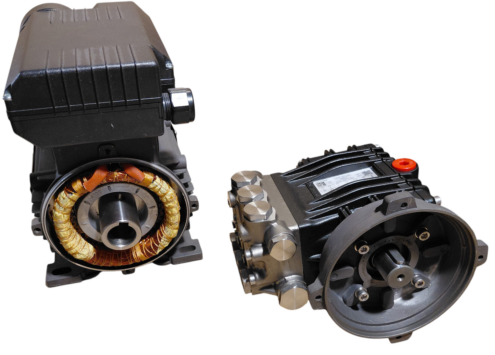
Assembling the high-pressure pump and motor is a straightforward mechanical operation that can be completed with normal hand tools. The exact procedure depends on the motor shaft configuration: some motors use a hollow shaft for direct coupling, while others use a standard male shaft combined with a flexible coupling and bellhousing.
The photographs accompanying this guide show each stage clearly. Before beginning, place the motor and pump on a clean, stable surface and confirm that all supplied screws, washers, fittings and coupling parts are available.
🧰 1. Tools and Materials Required
- Correctly sized Allen keys
- Open-ended or adjustable spanners
- Suitable assembly grease
- PTFE tape for the low-pressure inlet fitting only
- The supplied high-pressure sealing washer
- Screwdriver suitable for the electrical terminal cover
- All original screws supplied with the pump, motor and bellhousing
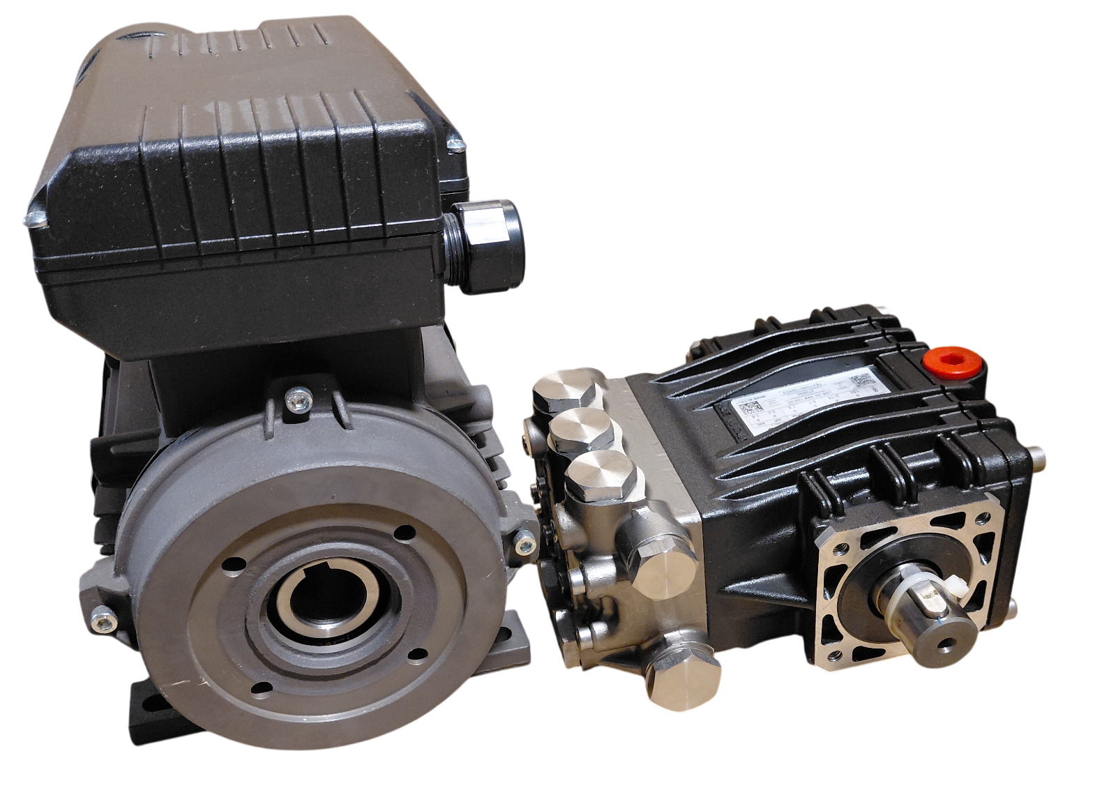
⚙️ 2. Identify the Motor Shaft Type
Before starting, identify which of the following motor configurations you have:
- Hollow-shaft motor: The male shaft of the high-pressure pump fits directly inside the hollow motor shaft.
- Male-shaft motor: The pump and motor are connected through a flexible coupling housed inside a bellhousing.
🕳️ 3. Assembly with a Hollow-Shaft Motor
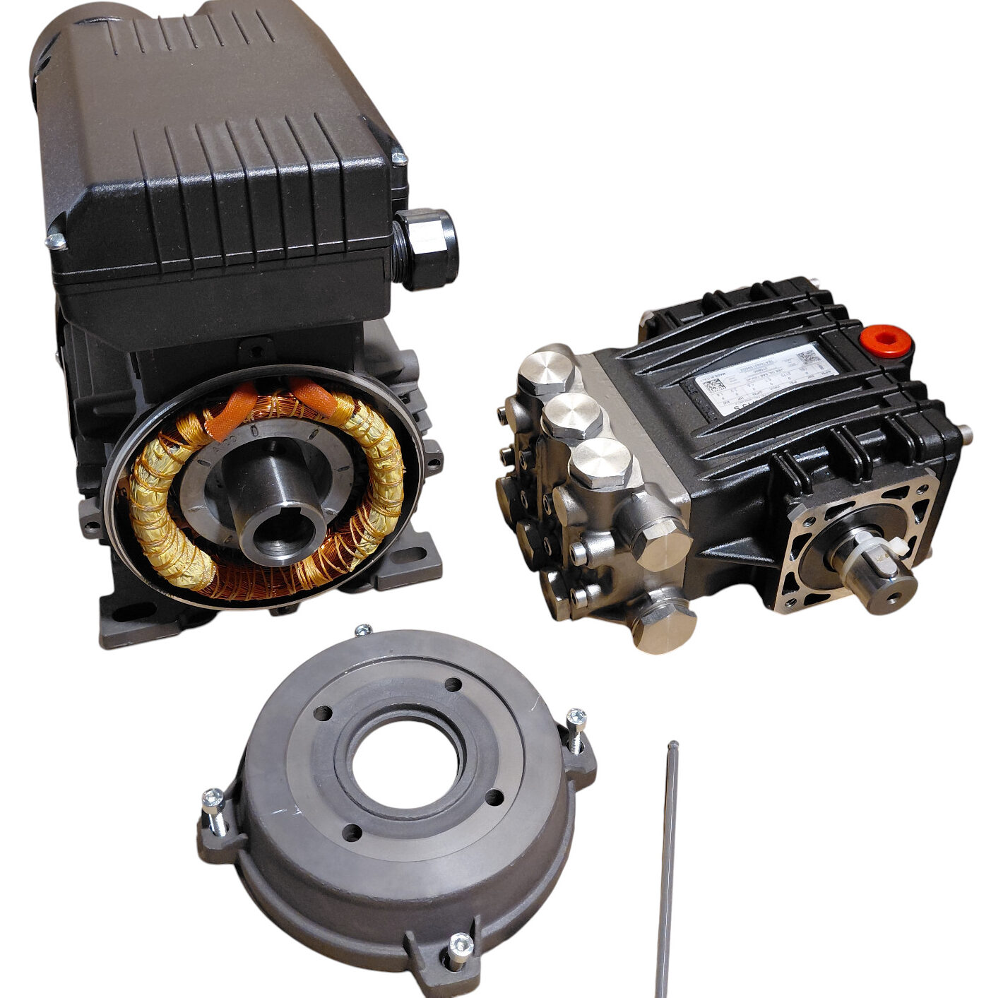
Step 1 — Remove the Motor Front Flange
Place the motor securely on the work surface. Remove the four Allen screws holding the front flange to the motor body, then carefully lift the flange away.
Step 2 — Attach the Flange to the Pump
Position the removed flange against the high-pressure pump and align the four mounting holes. Fasten the flange to the pump using the four supplied screws.
Tighten the screws progressively and evenly rather than fully tightening one screw before the others.
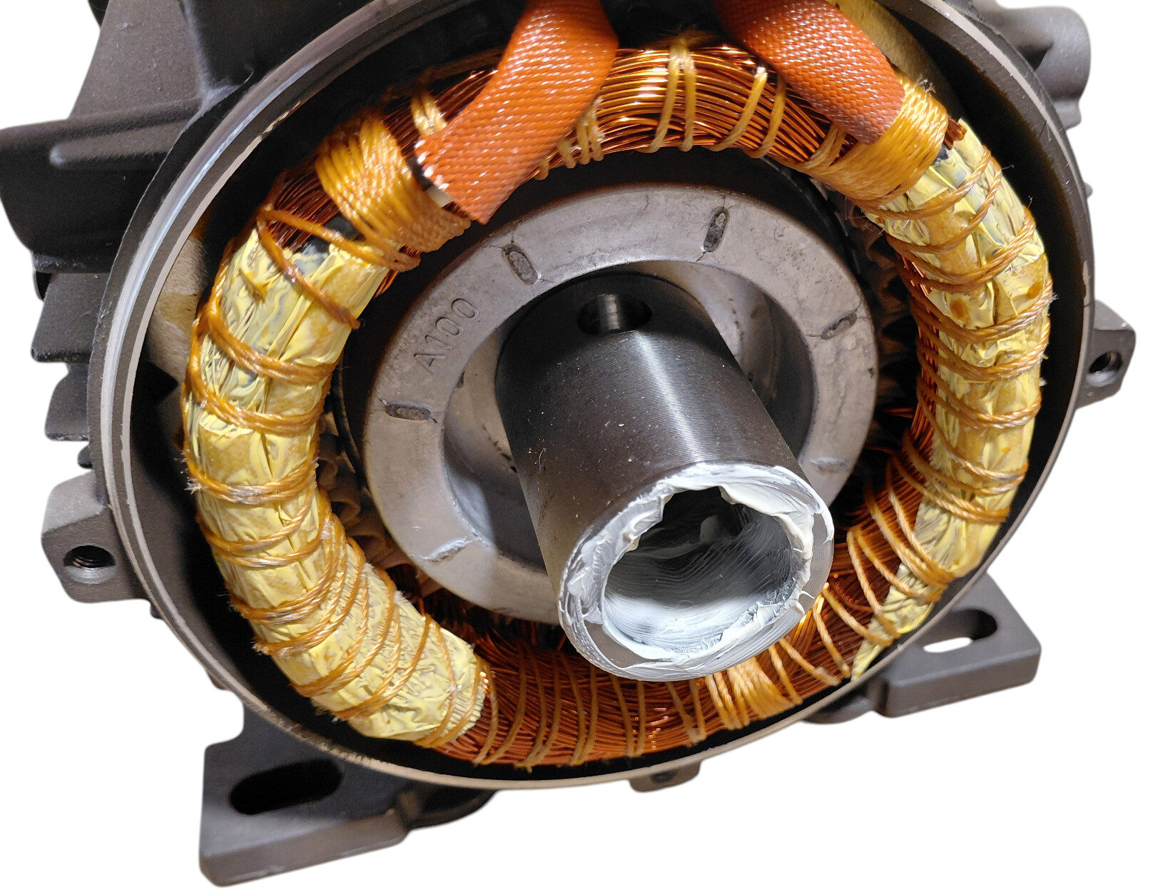
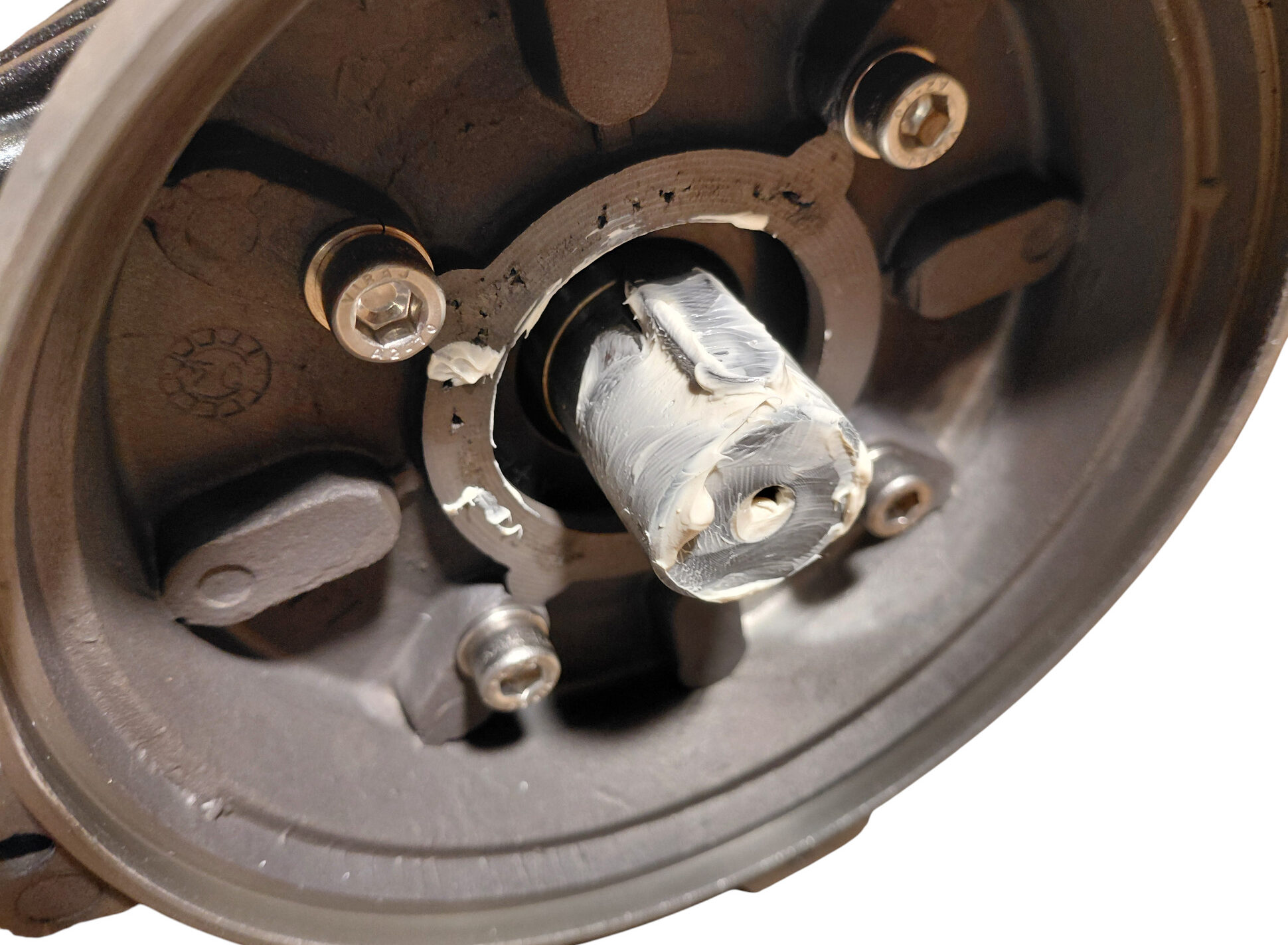
Step 3 — Lubricate the Shaft Connection
Apply a suitable layer of grease to:
- The male shaft of the high-pressure pump
- The internal surface of the hollow motor shaft
The grease helps the shafts slide together smoothly, prevents corrosion between the mating surfaces and makes future disassembly easier.
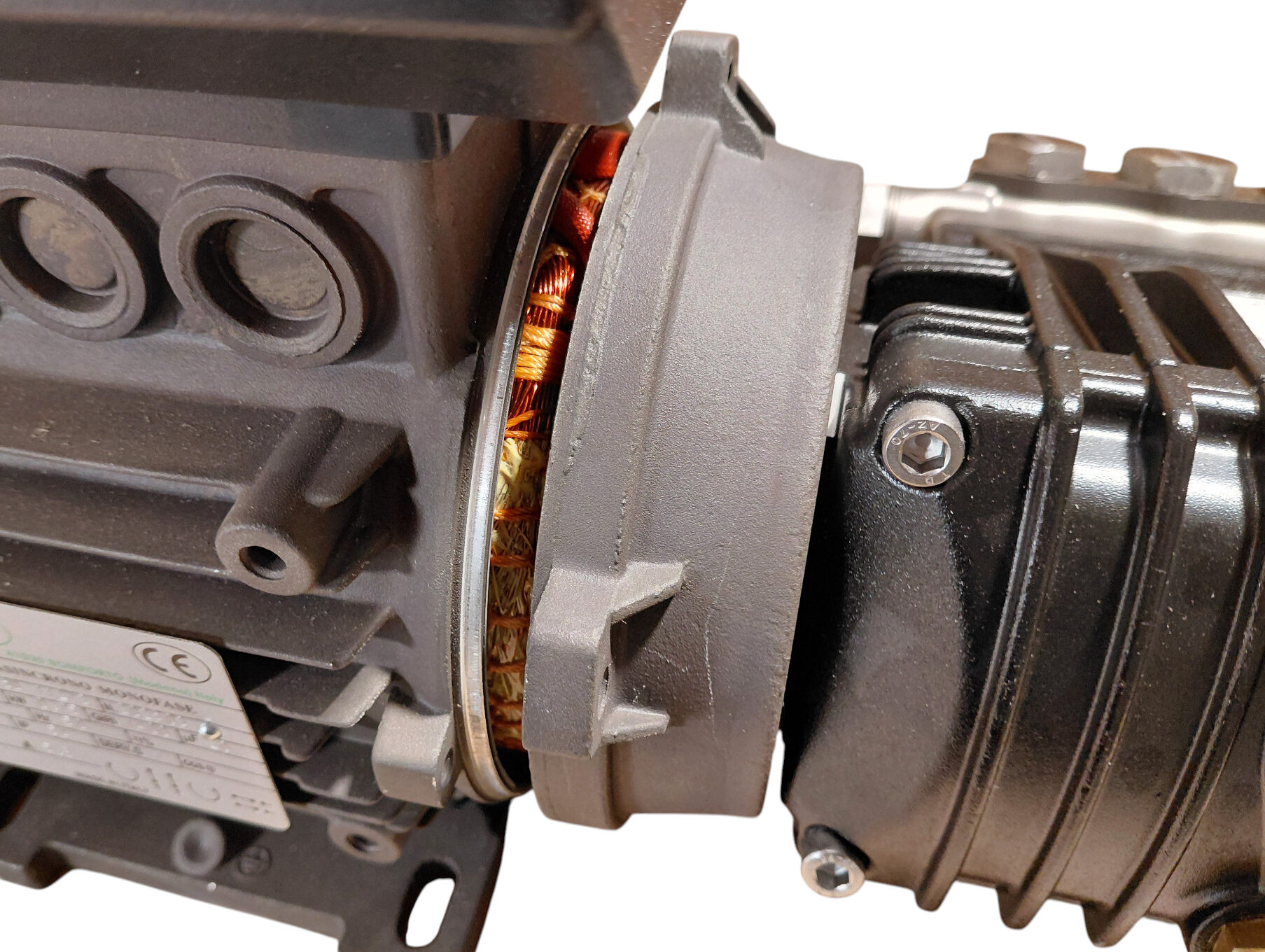
Step 4 — Insert the Pump Shaft into the Motor
Align the pump shaft carefully with the hollow motor shaft. Slide the pump and flange assembly straight into the motor without forcing or twisting it excessively.
The flange should approach the motor body evenly. If the shaft does not enter easily, remove the pump and check the alignment rather than using the mounting screws to pull the parts together.
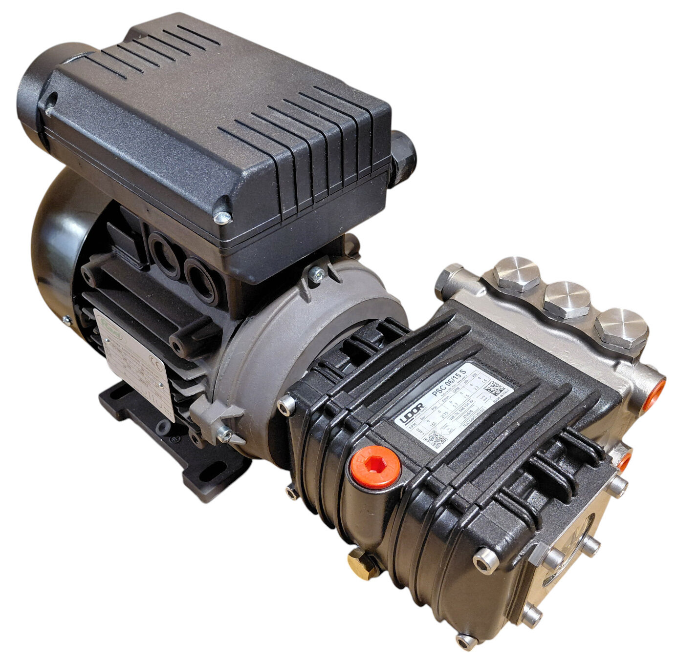
Step 5 — Refit the Flange to the Motor
Once the shaft is fully inserted and the flange is seated correctly, reinstall the four Allen screws that secure the flange to the motor.
Tighten them gradually in a cross pattern so that the flange remains evenly seated.
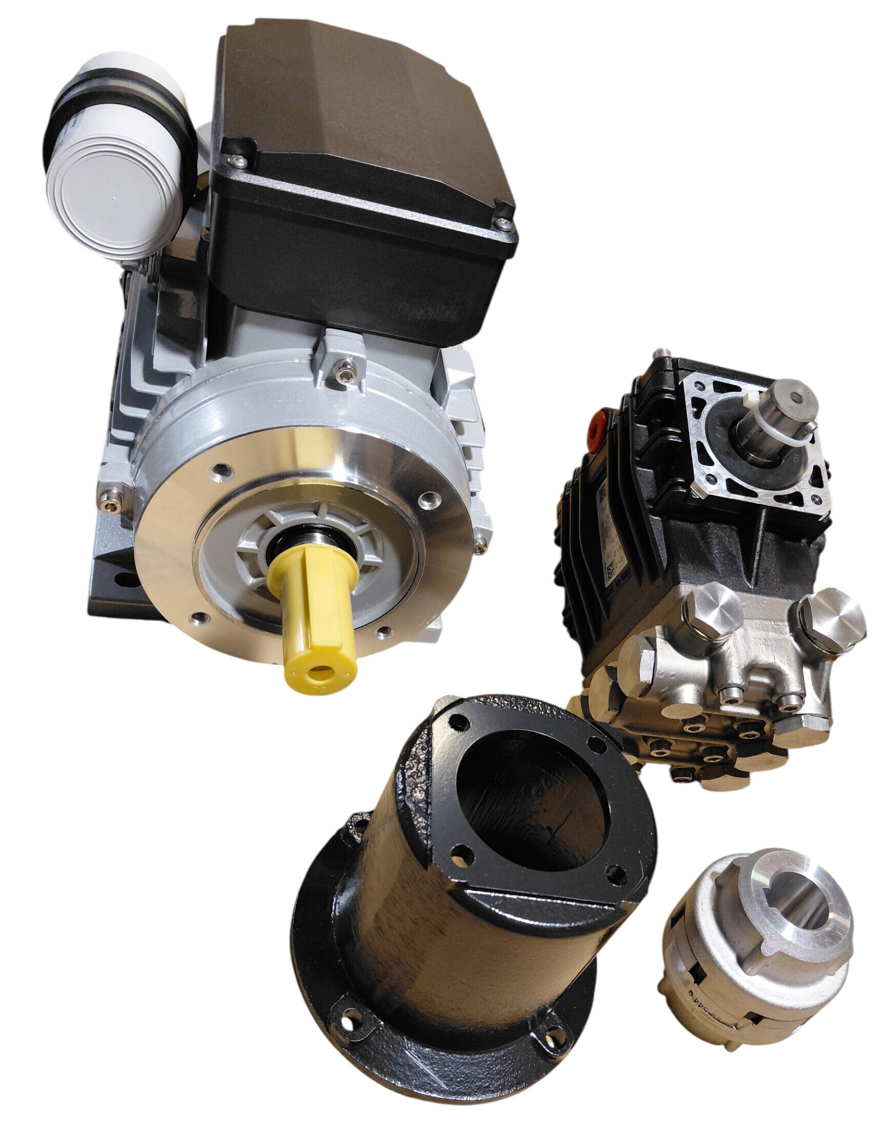
🔗 4. Assembly with a Male-Shaft Motor
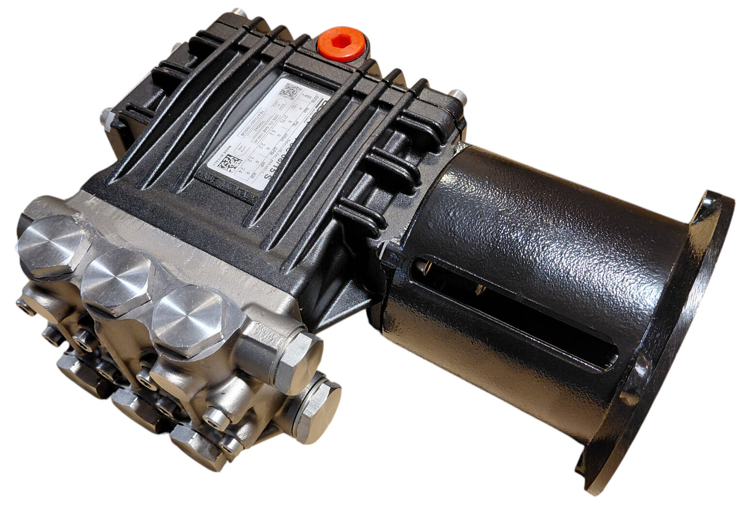
Step 1 — Attach the Bellhousing to the Pump
Align the bellhousing with the high-pressure pump and fasten it using the four supplied screws.
Tighten the screws evenly and confirm that the bellhousing is seated flat against the pump body.
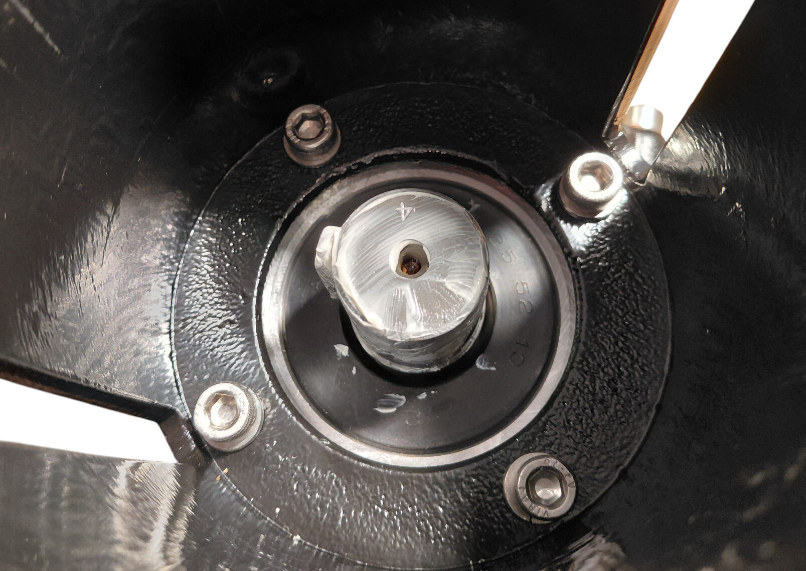
Step 2 — Lubricate the Shafts and Flexible Coupling
Apply a suitable layer of grease to:
- The male motor shaft
- The male pump shaft
- The internal coupling surfaces that slide over both shafts
This makes assembly easier and helps prevent corrosion between the shafts and coupling.
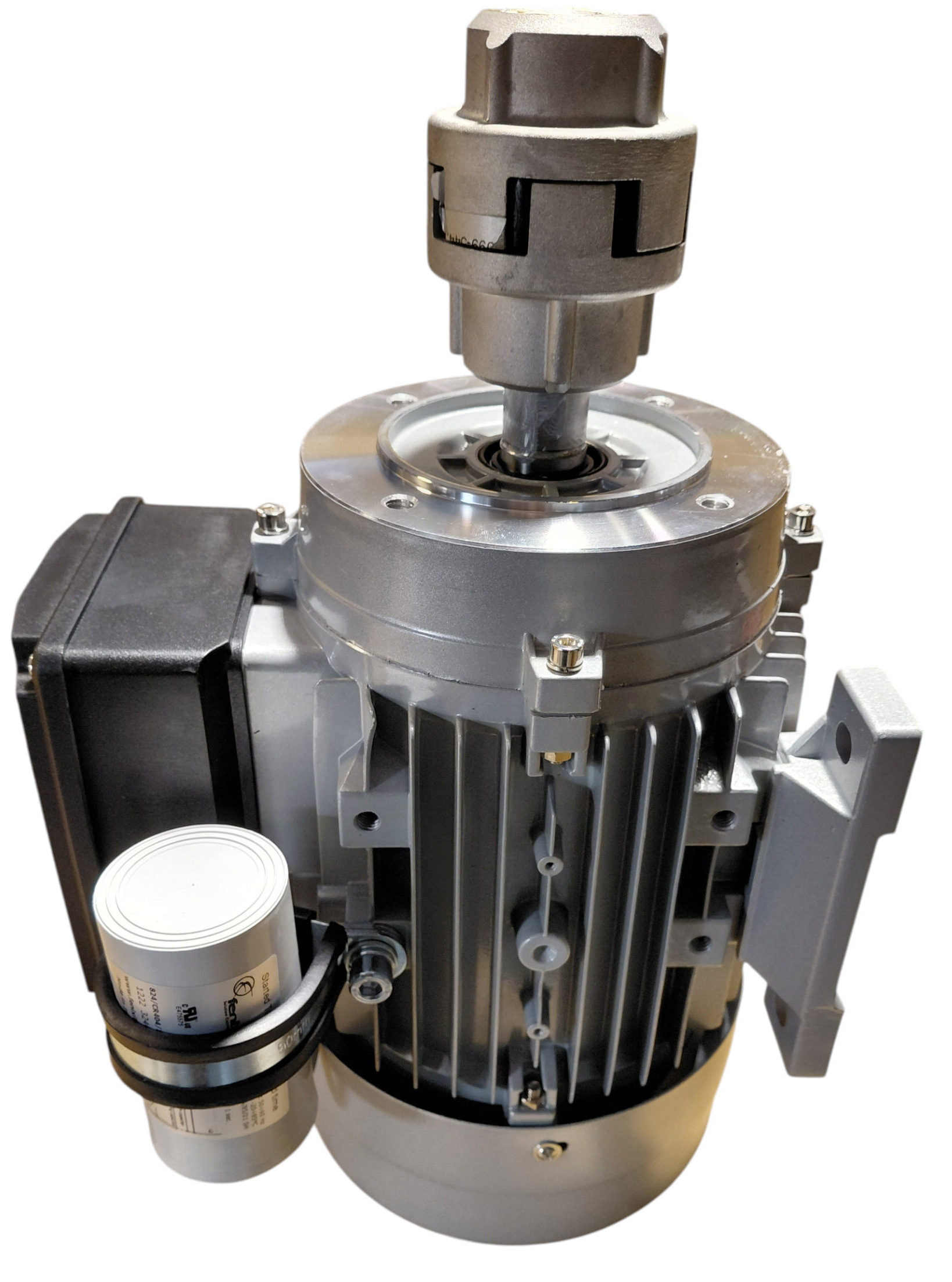
Step 3 — Fit the Flexible Coupling to the Motor
Place the motor vertically with the shaft facing upward. Fit the flexible coupling onto the motor shaft and make sure it is fully seated in the correct position.
Step 4 — Lower the Pump and Bellhousing onto the Motor
Hold the assembled pump and bellhousing above the motor. Carefully align the pump shaft with the upper side of the flexible coupling, then lower the assembly vertically.
The pump shaft should enter the coupling smoothly while the bellhousing approaches the motor mounting face.
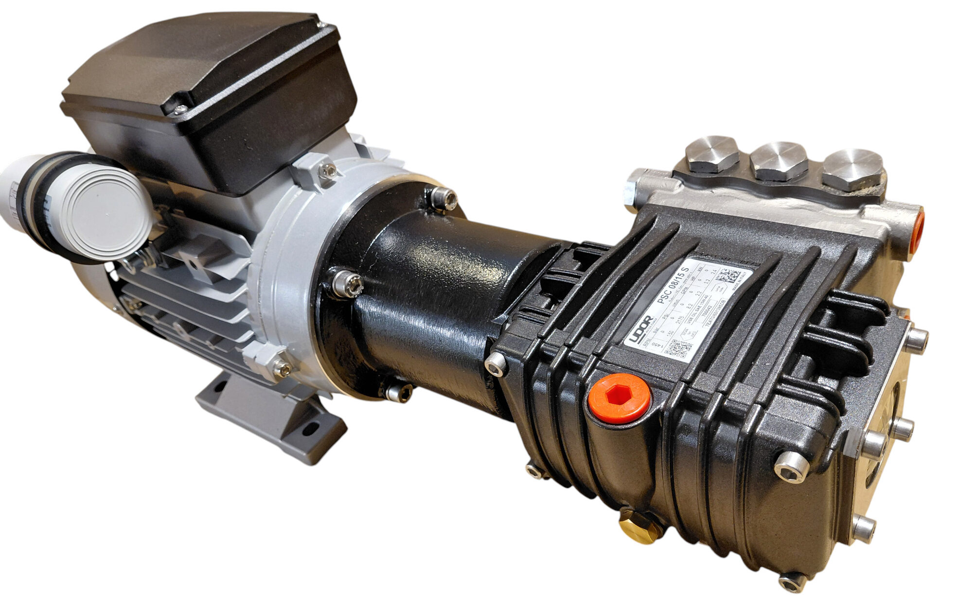
Step 5 — Secure the Bellhousing to the Motor
Once the coupling is correctly engaged and the bellhousing is fully seated, fasten the bellhousing to the motor body using the supplied screws.
Tighten them gradually in a cross pattern and confirm that there is no visible gap between the mating surfaces.
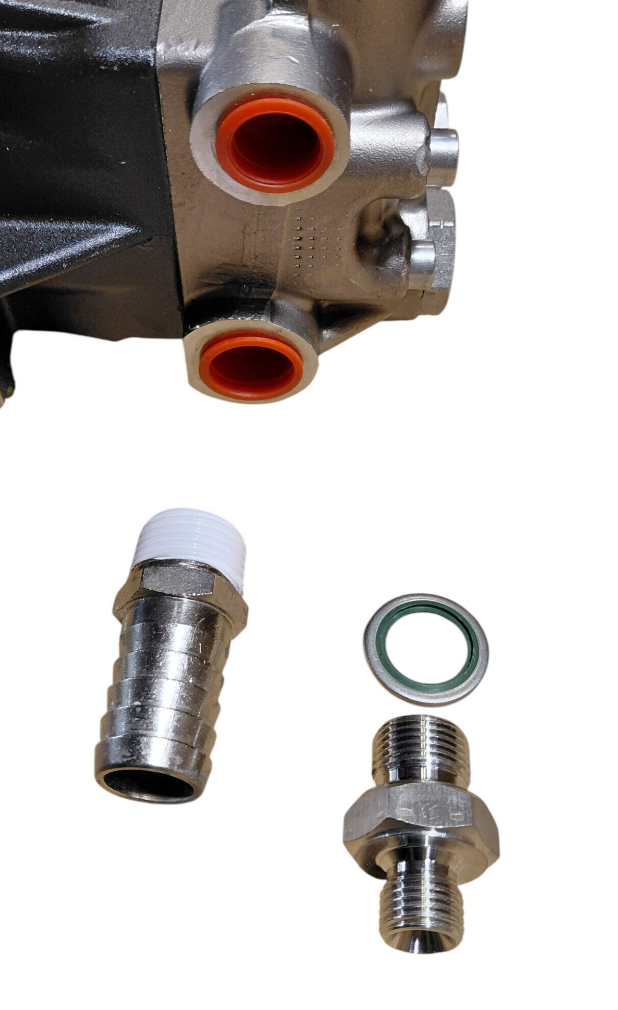
💧 5. Install the Low-Pressure Feed-Water Fitting
The low-pressure seawater inlet is located on the lower part of the pump head.
- Confirm that the inlet thread is clean and undamaged.
- Apply approximately two neat turns of PTFE tape to the male thread of the hose fitting.
- Keep the first thread reasonably clear so that loose tape cannot enter the pump.
- Screw the fitting into the lower pump inlet.
- Tighten it firmly but without excessive force.
🚿 6. Install the High-Pressure Outlet Nipple
The high-pressure outlet is located on the upper part of the pump head.
- Check that the supplied sealing washer is present and undamaged.
- Position the washer correctly on the high-pressure nipple.
- Screw the nipple into the upper outlet.
- Tighten it according to the supplied installation instructions.
The high-pressure nipple seals with the supplied washer, not on the thread. Adding PTFE tape can interfere with correct seating and may contaminate the high-pressure circuit.
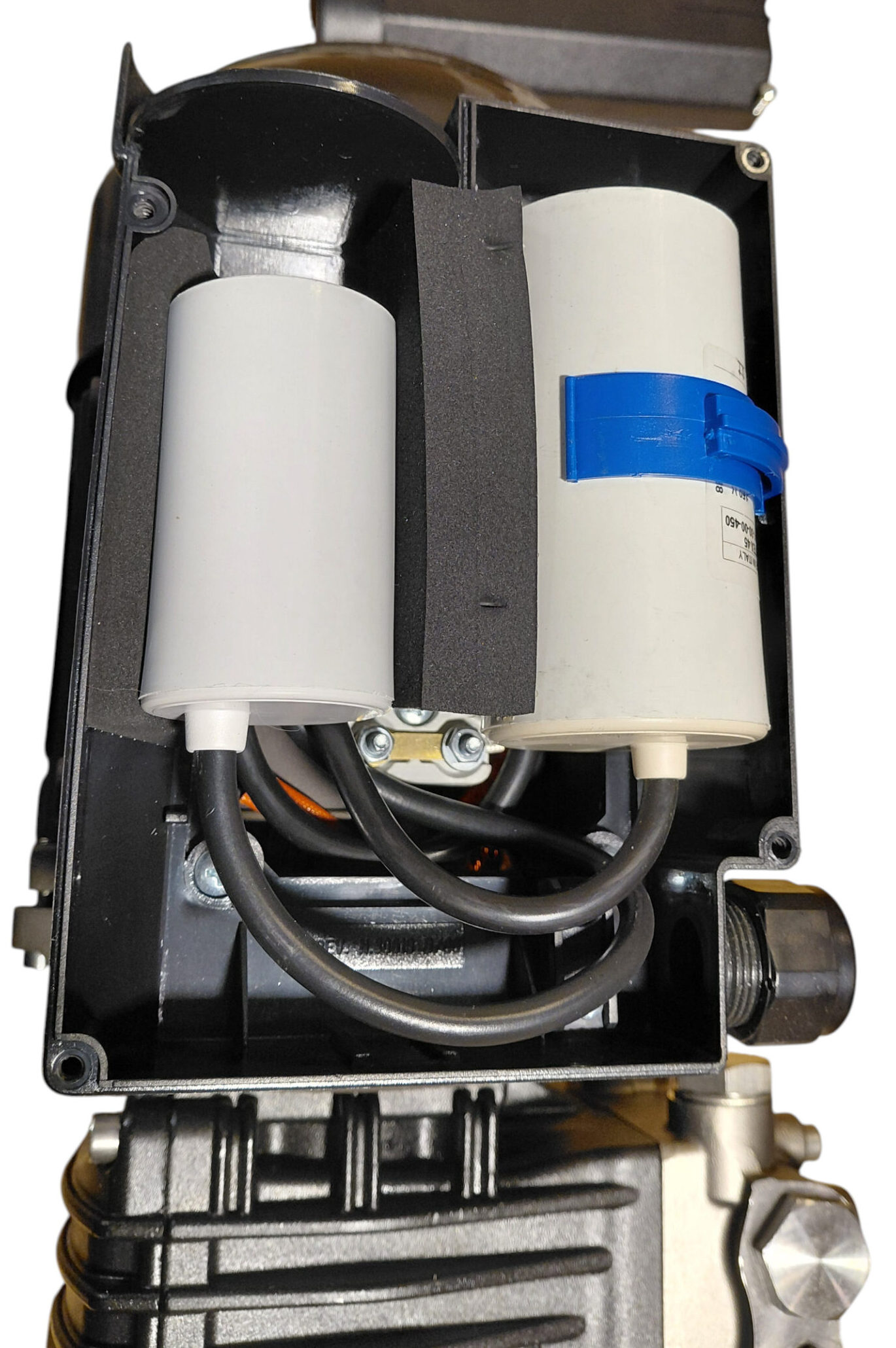
⚡ 7. Connect the Motor Power Cable
Remove the electrical terminal-box cover from the motor. If the capacitor assemblies obstruct access to the terminals, move them carefully aside without disconnecting or straining their wires.
Locate the two designated blade terminals used for the single-phase supply.
- Route the supply cable through the appropriate cable gland.
- Connect phase and neutral to the two designated blade terminals.
- On the specified BlueGold motor, the two supply connections are not polarity-sensitive, so phase and neutral may be connected in either order.
- Confirm that each terminal is fully inserted and secure.
- Arrange the wiring so that it cannot touch moving parts or be pinched by the cover.
- Return the capacitor assemblies to their original position.
- Refit and secure the terminal-box cover.
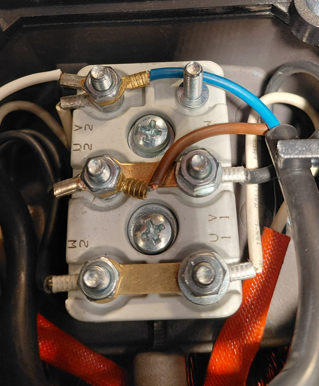
🔍 8. Final Mechanical Inspection
Before installing the assembly onboard, complete a final visual and mechanical check.
- All pump, flange and bellhousing screws are fitted and evenly tightened.
- The pump and motor are correctly aligned.
- No visible gap remains between the flange or bellhousing surfaces.
- The low-pressure fitting is installed in the lower inlet.
- The high-pressure nipple and sealing washer are installed in the upper outlet.
- No PTFE tape has been used on the washer-sealed high-pressure connection.
- The electrical cable is securely clamped by the cable gland.
- The terminal-box cover is correctly refitted.
- No tools, screws or packaging remain near the coupling or motor ventilation openings.
🛡️ 9. Before the First Startup
Mechanical assembly does not mean that the unit is ready to run dry on the workbench.
Before starting the motor:
- Mount the complete assembly securely.
- Connect the feed-water and high-pressure circuits.
- Confirm that the pump crankcase contains the correct oil, where applicable.
- Prime the feed circuit completely.
- Verify that seawater reaches the high-pressure pump without air.
- Leave the pressure-regulating valve open.
- Check the electrical supply voltage, fuse and protective devices.
- Confirm the correct rotation direction where required by the pump model.
✅ 10. Assembly Summary
| Motor configuration | Coupling method | Main assembly parts |
|---|---|---|
| Hollow shaft | Pump shaft inserted directly into motor shaft | Removable front flange and four fixing screws |
| Male shaft | Flexible coupling between pump and motor shafts | Bellhousing, flexible coupling and fixing screws |
| Feed-water inlet | Thread-sealed hose fitting | Approximately two turns of PTFE tape |
| High-pressure outlet | Washer-sealed nipple | Supplied sealing washer; no PTFE tape |
| Electrical supply | Single-phase connection | Phase and neutral on the designated motor terminals |
Lubricate and align the shafts carefully, never pull misaligned components together with the screws, use the correct sealing method on each hydraulic connection, and complete the electrical connection only according to the supplied motor diagram.
The reverse osmosis membrane and its pressure vessel form the core separation unit of every marine watermaker. This is where pressurised seawater is divided into two streams: freshwater that passes through the membrane and concentrated brine that continues toward the discharge.
Membrane format, active surface area, high-pressure pump flow and vessel configuration must all be selected together. A larger membrane does not automatically guarantee greater production, and adding more membranes does not compensate for insufficient pump flow.
💧 1. What an RO Membrane Does
A seawater reverse osmosis membrane is a spiral-wound element containing multiple layers of semi-permeable material around a central product-water tube.
When seawater flows across the membrane surface under sufficient pressure:
- Water molecules pass through the membrane and enter the central product-water tube.
- Most dissolved salts remain in the feed stream and leave the element as concentrated brine.
- Suspended particles should already have been removed by the seawater strainer and prefilters.
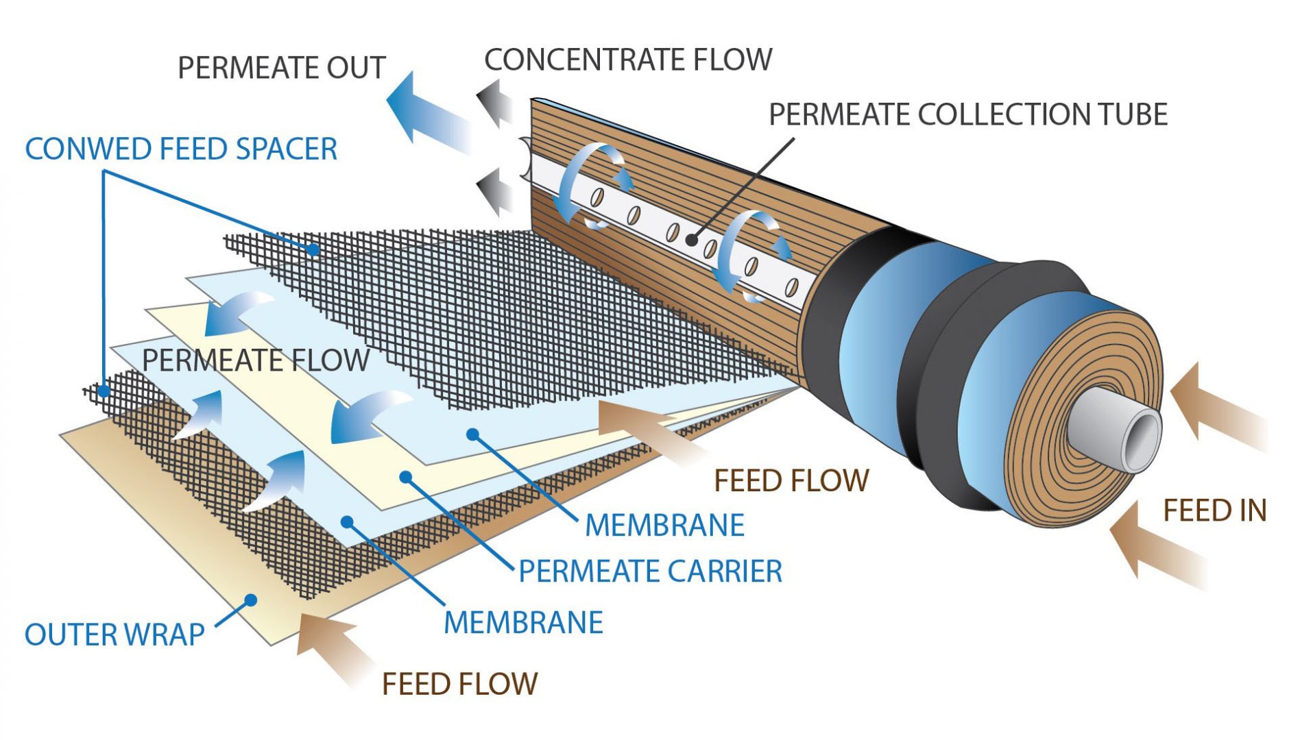
🛡️ 2. What the Pressure Vessel Does
The pressure vessel safely contains the membrane and the high-pressure seawater flowing around it. It also supports the end caps, seals and product-water connections that keep the freshwater and brine streams separated.
A suitable marine pressure vessel must provide:
- Safe operation at the maximum possible system pressure.
- Resistance to seawater corrosion.
- Reliable sealing around the end plugs and product-water tube.
- Correct internal dimensions for the selected membrane format.
- Access for membrane installation, removal and maintenance.
- Strong and secure mounting aboard the vessel.

📐 3. Understanding Membrane Format Numbers
Marine RO membranes are normally identified by a four-digit format number.
- The first two digits indicate the approximate membrane diameter in tenths of an inch.
- The last two digits indicate the approximate membrane length in inches.
2521 = approximately 2.5 inches in diameter and 21 inches long.
2540 = approximately 2.5 inches in diameter and 40 inches long.
3021 = approximately 3 inches in diameter and 21 inches long.
📏 4. The 2521 Format
The 2521 membrane is compact and particularly useful where installation space is limited or where several short vessels can be distributed around the boat.
Main Characteristics
- Approximately 2.5 inches in diameter and 21 inches long.
- Easy to handle and replace in confined machinery spaces.
- Suitable for small and medium modular systems.
- Multiple elements can be combined to increase total membrane area.
- Useful where a long 40-inch vessel cannot be installed.
📏 5. The Traditional 2540 Format
The 2540 membrane has the same nominal diameter as a 2521 element but almost twice the length. Its larger active area allows one element to replace several smaller membranes in many configurations.
Main Characteristics
- Approximately 2.5 inches in diameter and 40 inches long.
- High active membrane area in a single element.
- Well suited to medium- and high-output watermakers.
- Uses fewer vessels and interconnecting high-pressure hoses than multiple 2521 elements.
- Requires a long, straight installation space and enough clearance for membrane removal.

🆕 6. The Compact High-Capacity 3021 Format
The 3021 format combines the short length of a 2521 membrane with a larger three-inch diameter. The increased diameter provides substantially more active membrane area without requiring a traditional 40-inch vessel.
The BlueGold 3021 pressure vessel is specifically designed for 3 × 21-inch seawater membranes and offers a modern alternative to conventional 2540 or multiple-2521 arrangements.
Main Advantages
- Compact length: Easier to install in lockers and machinery spaces where a 40-inch vessel will not fit.
- Large active membrane area: Production potential comparable to traditional 2540 configurations, depending on membrane model and operating conditions.
- Simpler installation: One short vessel can replace a longer vessel or a more complex multi-vessel rack.
- Easier service access: The shorter membrane can be removed with less longitudinal clearance.
- Reduced plumbing complexity: Fewer high-pressure interconnections may be required.
- Suitable for modern energy-recovery systems: Particularly attractive where compactness and membrane area are both important.
⚖️ 7. Comparing the Three Formats
| Format | Approximate size | Main advantage | Typical limitation |
|---|---|---|---|
| 2521 | 2.5″ × 21″ | Compact, modular and easy to distribute onboard | Several membranes may be needed for higher output |
| 2540 | 2.5″ × 40″ | Large active area in one widely used standard element | Requires a long installation and removal space |
| 3021 | 3″ × 21″ | High membrane area in a short, serviceable format | Requires a dedicated 3021 vessel and compatible components |
🔄 8. Single or Multiple Membranes?
Several smaller membranes can be connected to obtain the total active surface required by the system. The correct arrangement depends on pump flow, desired production, pressure loss and installation space.
Multiple vessels may offer excellent layout flexibility, but they also introduce more:
- High-pressure hoses and fittings.
- Product-water connections.
- End-plug seals and O-rings.
- Mounting brackets.
- Potential leak points.
A single larger membrane or compact 3021 element simplifies plumbing, while multiple 2521 vessels may fit more easily around irregular spaces.

🚰 9. Pump Flow and Membrane Area
The high-pressure pump must provide enough flow across the membrane surface to produce freshwater while carrying rejected salts away in the brine stream.
Too little flow can lead to:
- Insufficient cross-flow along the membrane.
- Excessive recovery from the available feed water.
- Higher salt concentration near the membrane surface.
- Scaling, fouling and reduced membrane life.
- Unstable freshwater production.
Excessive pump flow can increase motor power, pressure loss and brine volume without providing a proportional increase in freshwater output.
📊 10. Typical Conventional BlueGold Configurations
The following values are practical estimates for conventional high-pressure pump systems. Actual output depends on the membrane model, seawater temperature, salinity, operating pressure and membrane condition.
| Membrane configuration | High-pressure pump flow | Typical production | Indicative motor rating |
|---|---|---|---|
| 2 × 2521 | 4 L/min | Approximately 50–60 L/h | Approximately 0.5–0.75 kW |
| 2 × 2521 | 6 L/min | Approximately 60 L/h | 0.75 kW |
| 3 × 2521 | 6 L/min | Approximately 80 L/h | 0.75 kW |
| 4 × 2521 | 11 L/min | Approximately 130–150 L/h | 1.5 kW |
| 1 × 2540 | 6–11 L/min | Approximately 60–90 L/h | 0.75–1.5 kW |
| 2 × 2540 | 6–11 L/min | Approximately 100–150 L/h | 0.75–1.5 kW |
| 3 × 2540 | 13 L/min | Approximately 200 L/h | 2.2 kW |
| 4 × 2540 | 13 L/min | Approximately 240 L/h | 2.2 kW |
🧱 11. Vessel Materials and Construction
Marine pressure vessels may be manufactured from stainless steel, reinforced composite or other materials specifically rated for seawater reverse osmosis pressure.
Composite Vessels
- Lightweight and corrosion-resistant.
- Easy to handle during installation.
- Well suited to marine environments.
- Require protection from mechanical damage and incorrect clamping.
Stainless-Steel Vessels
- Very strong and mechanically robust.
- Can provide excellent durability when manufactured from suitable alloys.
- Heavier than composite alternatives.
- Require attention to galvanic corrosion and mounting materials.
🛠️ 12. Installation Planning
Before choosing a membrane format, measure the complete space required—not only the length of the vessel.
Allow room for:
- End caps and high-pressure fittings.
- Product-water connections.
- Hose bend radius.
- Mounting brackets.
- Removal of the end plug.
- Withdrawal of the full membrane element.
- Inspection and O-ring replacement.
✅ 13. Selection Checklist
- Determine the freshwater production required.
- Confirm the available high-pressure pump flow.
- Choose the membrane format and active area.
- Select a vessel specifically compatible with that format.
- Check maximum operating-pressure ratings.
- Allow adequate brine flow and avoid excessive recovery.
- Confirm the available installation and membrane-removal space.
- Use pressure-rated hoses and fittings.
- Keep vessels accessible for flushing, cleaning and replacement.
- Follow the actual membrane manufacturer’s data sheet.
The 2521 format offers maximum modular flexibility, the 2540 remains a proven high-capacity standard, and the new 3021 format provides comparable membrane area in a much shorter and more practical package.
The production stated on a membrane data sheet is not a fixed quantity that will be obtained in every sea and season. Freshwater flow and product-water salinity change with feed-water temperature, seawater salinity, operating pressure, membrane age and system recovery.
Understanding these effects prevents unnecessary membrane replacement and helps distinguish normal seasonal variation from a real system problem.

🧪 1. Membrane Test Conditions
Membrane manufacturers publish nominal production and salt-rejection values under specified laboratory test conditions.
These usually define:
- Feed-water salinity.
- Feed-water temperature.
- Applied pressure.
- Recovery rate.
- Feed-water pH.
For small seawater membranes, typical reference conditions are often around 25°C and approximately 32,000–35,000 ppm salinity, but the exact pressure and other parameters depend on the membrane model.
🌡️ 2. Effect of Feed-Water Temperature
Water becomes more viscous as temperature decreases. Cold water therefore passes through the membrane less easily, reducing product-water flow.
As seawater becomes warmer, viscosity decreases and permeate flow increases.
As Temperature Increases
- Freshwater production normally increases.
- Salt passage generally increases.
- Product-water TDS may rise.
As Temperature Decreases
- Freshwater production decreases.
- Salt passage generally decreases.
- Product-water TDS may improve.
Approximate examples often encountered in practice include:
- At around 30–32°C, production may be noticeably above the nominal 25°C value.
- At around 15°C, production may fall by approximately one third.
- At around 10°C, production may approach half of the warm-water value, depending on membrane model and operating conditions.
🧮 3. Temperature Correction Factors
A temperature correction factor can be used to estimate production away from the membrane’s standard reference temperature.
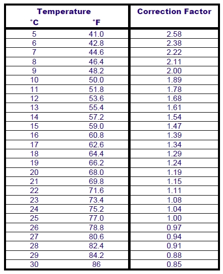
Example
Assume a system is rated at 120 litres per hour at 25°C and the applicable correction factor at 15°C is 1.47.
The expected production at 15°C is therefore approximately 82 litres per hour, even though the membrane and pump are operating normally.
🧂 4. Effect of Feed-Water Salinity
Dissolved salt creates osmotic pressure, which opposes the pressure applied by the high-pressure pump.
As feed-water salinity increases, more of the applied hydraulic pressure is required simply to overcome osmotic pressure. Less effective pressure remains available to produce freshwater.
As Salinity Increases
- Freshwater production decreases.
- Product-water TDS generally increases.
- More pressure may be needed to obtain the same production.
- Motor and pump load may increase if pressure is raised.
As Salinity Decreases
- Freshwater production increases.
- Product-water TDS generally decreases.
- The same output can often be achieved at lower pressure.
Salinity can be checked with a suitable refractometer or conductivity instrument. Measurements should be made on the actual seawater entering the watermaker rather than assumed from a general regional value.
💥 5. Effect of Operating Pressure
Increasing applied pressure raises the net driving force across the membrane. Within the permitted operating range, this generally increases freshwater flow and improves salt rejection.
As Pressure Increases
- Freshwater production normally increases.
- Product-water TDS generally decreases.
- Pump shaft power increases.
- Motor current and heat production increase.
- Mechanical stress on the complete high-pressure circuit increases.
As Pressure Decreases
- Freshwater production decreases.
- Product-water TDS generally increases.
- Motor and pump load decrease.
Increasing operating pressure from 55 to 60 bar raises the hydraulic power requirement by approximately nine percent at the same pump flow. This extra power becomes additional motor current and heat.
⚖️ 6. Net Driving Pressure
Membrane production depends not only on gauge pressure but on the pressure remaining after osmotic resistance and product-side pressure are considered.
In simplified terms:
This explains why two systems operating at the same gauge pressure can produce different quantities of freshwater when salinity or product-side pressure differs.
🚰 7. Product-Water Backpressure
The freshwater outlet should normally discharge freely toward the flow meter, diversion valve and tank.
Restrictions or pressure on the product-water side reduce the effective pressure across the membrane and can damage membrane seals if excessive.
Possible causes include:
- Undersized product-water tubing.
- Blocked flow meters.
- Closed or incorrectly positioned valves.
- Pressurised freshwater tanks connected without suitable separation.
- Check valves with excessive opening pressure.
📈 8. Why TDS Changes
Product-water TDS is influenced by both membrane salt rejection and the quantity of water passing through the membrane.
TDS may increase because of:
- Higher feed-water salinity.
- Higher feed-water temperature.
- Insufficient operating pressure.
- Membrane ageing or chemical damage.
- Damaged O-rings or product-water seals.
- Excessive recovery.
- High product-water backpressure.
🔍 9. Flow Loss Is Not Always Membrane Fouling
Reduced freshwater production may be caused by conditions outside the membrane itself.
Before suspecting fouling, check:
- Feed-water temperature.
- Feed-water salinity.
- High-pressure pump flow.
- Actual operating pressure.
- Prefilter condition.
- Feed-pump performance.
- Air entering the suction line.
- Motor voltage and rotational speed.
- Brine flow and recovery ratio.
🧫 10. Fouling, Scaling and Ageing
Over time, membrane performance may decline because of:
- Suspended-particle fouling.
- Biological growth and biofilm.
- Organic contamination.
- Mineral scaling.
- Oxidant or chlorine damage.
- Incorrect cleaning chemicals.
- Mechanical seal damage.
- Normal membrane ageing.
Fouling commonly reduces product-water flow and increases pressure loss. Chemical damage or mechanical leakage may instead produce an abrupt increase in TDS.
📝 11. Recommended Operating Log
| Parameter | Why record it? |
|---|---|
| Date and operating hours | Tracks service intervals and membrane age |
| Feed-water temperature | Allows production to be temperature-corrected |
| Feed-water salinity | Explains changes in output and TDS |
| Operating pressure | Confirms the membrane’s driving pressure |
| Feed or pump flow | Identifies pump or restriction problems |
| Product-water flow | Tracks normalized membrane performance |
| Brine flow | Allows recovery to be checked |
| Product-water TDS | Monitors salt rejection and mechanical sealing |
📋 12. Quick Effect Summary
| Change | Effect on production | Typical effect on TDS | Other consequence |
|---|---|---|---|
| Higher temperature | Increases | Usually increases | More salt passage |
| Lower temperature | Decreases | Usually decreases | Higher viscosity |
| Higher salinity | Decreases | Increases | Higher osmotic pressure |
| Lower salinity | Increases | Decreases | Lower pressure may be sufficient |
| Higher operating pressure | Increases | Usually decreases | Higher motor load and heat |
| Lower operating pressure | Decreases | Usually increases | Lower motor load |
Temperature, salinity and pressure can change production and TDS substantially even when the membrane is in perfect condition. Measure the operating conditions, correct the expected output and look for long-term trends before deciding that cleaning or replacement is necessary.
BlueGold 2.5-inch and 3-inch pressure vessels perform the same basic function, but their construction and assembly details are different. For this reason, each vessel type should be assembled according to its own dedicated procedure.
This guide describes the components and assembly sequence of the BlueGold 2.5-inch pressure vessel for standard 2521 or 2540 seawater reverse osmosis membranes.
Install the brine-side end cap first → insert the membrane from the feed side in the correct flow direction → install the feed-side end cap last.
📦 1. Components Included
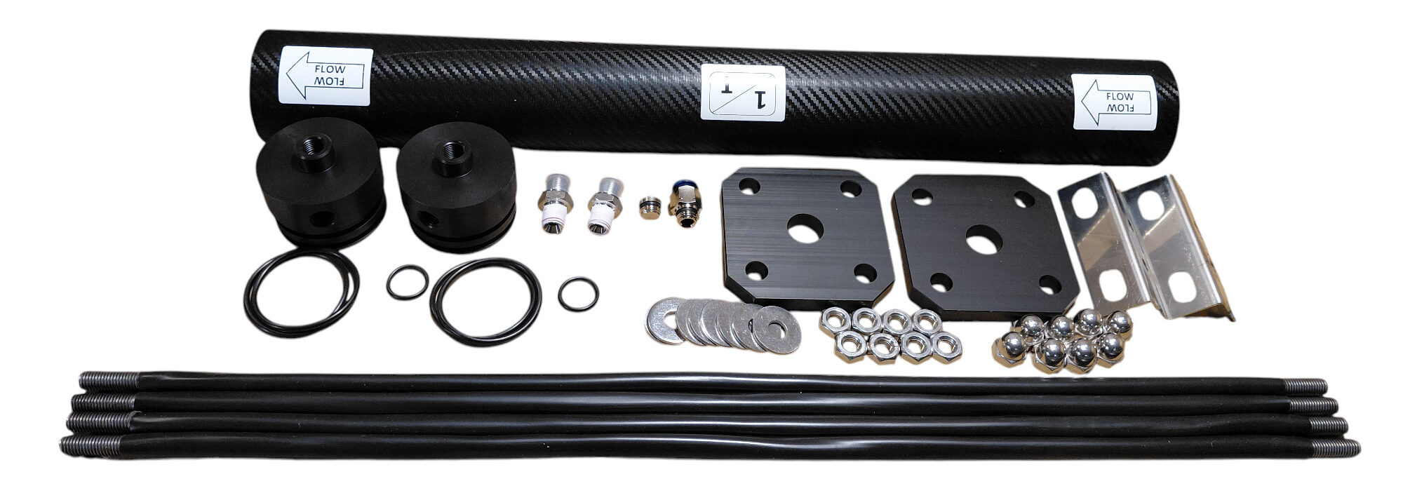
A standard single-membrane BlueGold 2.5-inch pressure-vessel assembly includes:
- 1 pressure tube: Supplied in either 21-inch or 40-inch length, depending on the selected membrane.
- 2 Delrin end caps: One for the feed end and one for the brine end.
- 4 external O-rings: These seal the end caps against the internal wall of the pressure tube.
- 2 internal O-rings: These seal the membrane’s central permeate tube inside the end caps.
- 2 nipples, ¼″ NPT × ¼″ BSPP: Used for the high-pressure feed and brine connections.
- 1 permeate-side plug: Used to close one of the two product-water outlets.
- 1 John Guest ¼″ push-fit connector: Used for the product-water tube.
- 2 aluminium closure plates: Positioned outside the end caps to retain the complete assembly.
- 4 stainless-steel tie rods with protective PVC coating.
- 8 stainless-steel washers, 10 × 30 mm.
- 8 stainless-steel M10 nuts.
- 8 stainless-steel M10 cap nuts.
- 2 stainless-steel mounting brackets.
- 1 set of flow-direction and identification labels.
🧰 2. Tools and Materials Required
- Suitable open-ended or adjustable spanners
- Clean silicone grease compatible with potable-water and membrane applications
- PTFE thread-sealing tape
- Clean lint-free cloth
- Marker for temporarily identifying flow direction
- Clean freshwater for rinsing components if required
➡️ 3. Mark the Flow Direction
Before installing any internal component, identify the intended feed and brine ends of the pressure tube.
Mark the direction of seawater flow temporarily on the outside of the tube:
The supplied permanent labels can be applied after assembly has been completed and the final orientation has been confirmed.
🔩 4. Install the High-Pressure Nipples in the End Caps
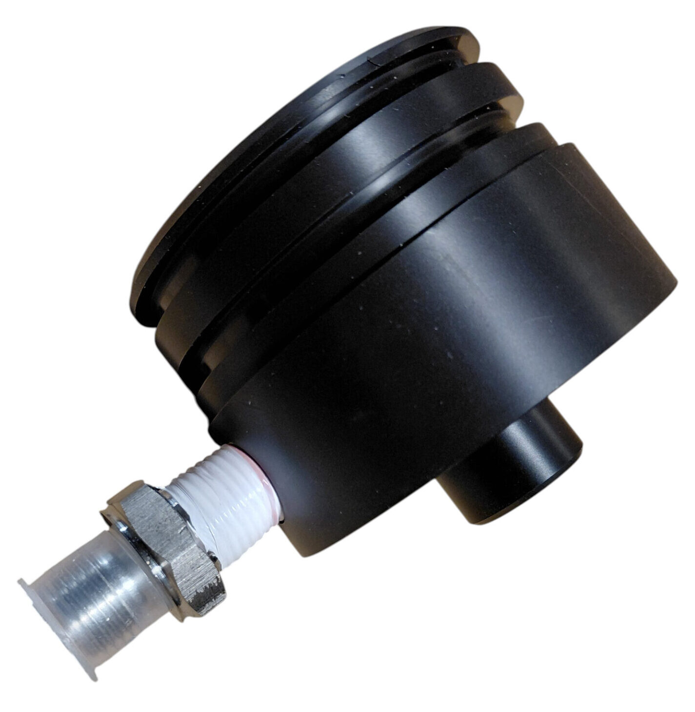
Each end cap receives one ¼″ NPT × ¼″ BSPP nipple for the high-pressure seawater connection.
- Identify the tapered ¼″ NPT side of the nipple.
- Apply approximately two neat turns of PTFE tape to the NPT thread.
- Keep the first thread reasonably clear so that loose tape cannot enter the hydraulic circuit.
- Screw the NPT side into the threaded port of the Delrin end cap.
- Tighten firmly, but do not apply excessive torque.
⭕ 5. Install the End-Cap O-Rings
Prepare both end caps before inserting either of them into the pressure tube.
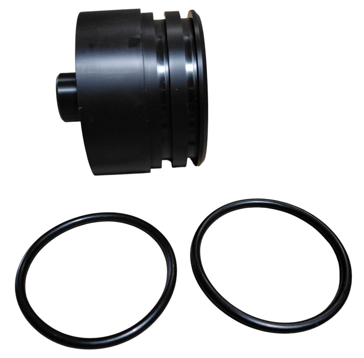
External O-Rings
Fit the two large external O-rings into their respective grooves around each end cap.
Check that:
- The O-rings are not twisted.
- They sit fully inside their grooves.
- No part of the seal is pinched or stretched.
- The grooves are clean and free from debris.
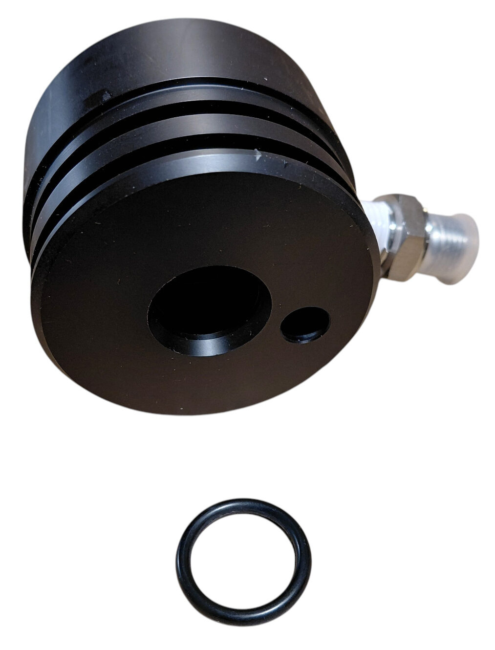
Internal Permeate-Tube O-Ring
Install the smaller internal O-ring into the central bore of each end cap. This O-ring seals against the permeate tube protruding from the centre of the membrane.
🧴 6. Lubricate the Sealing Surfaces
Apply a light, continuous film of silicone grease to:
- The external end-cap O-rings.
- The internal permeate-tube O-ring.
- The internal wall of the pressure tube near each open end.
The grease should make the surfaces smooth and slippery without leaving large deposits.
🚿 7. Install the Brine-Side End Cap First
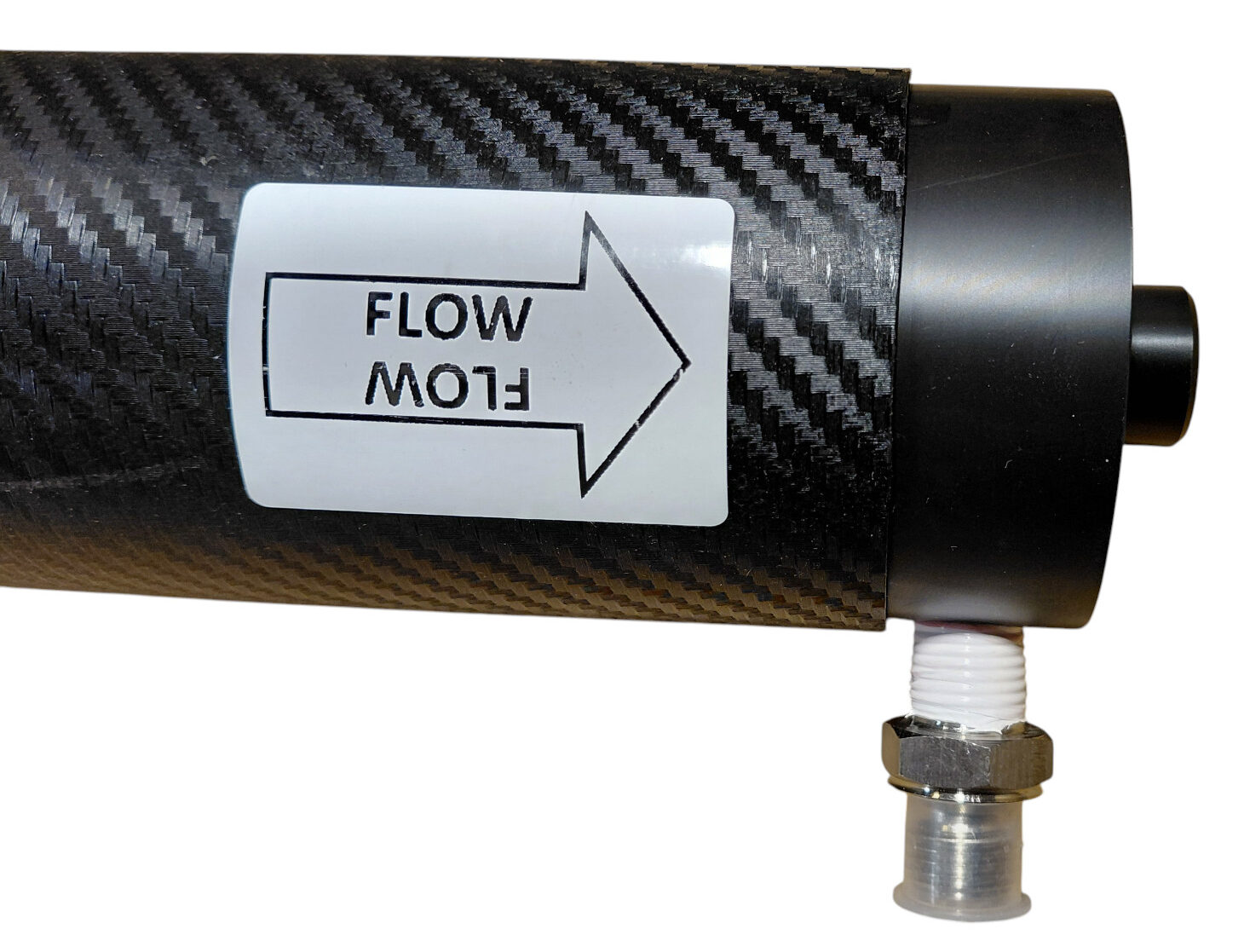
Identify the end of the vessel marked as the brine outlet.
Insert the prepared end cap into this end of the pressure tube. Push it inward evenly and keep it square to the tube.
The end cap should enter smoothly as the lubricated external O-rings pass inside the vessel.
🧬 8. Prepare the Membrane
Inspect the seawater membrane before installation.
Confirm that:
- The membrane format matches the vessel length.
- The membrane wrapper is undamaged.
- The central permeate tube is clean.
- The brine seal is correctly seated.
- The flow-direction arrow is clearly visible.
Apply a light film of silicone grease to:
- The membrane brine-seal O-ring or lip seal.
- Both ends of the central permeate tube.
- The internal surface of the open feed end of the pressure vessel.
➡️ 9. Insert the Membrane from the Feed Side
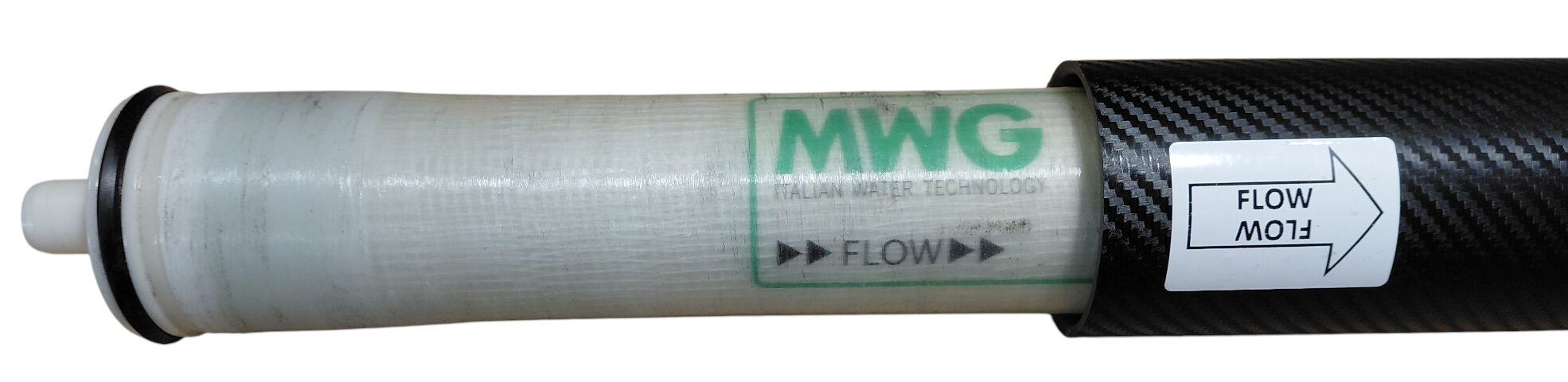
The membrane must be inserted from the end of the vessel that has remained open: the feed side.
Align the flow-direction arrow printed on the membrane with the flow direction previously marked on the pressure tube.
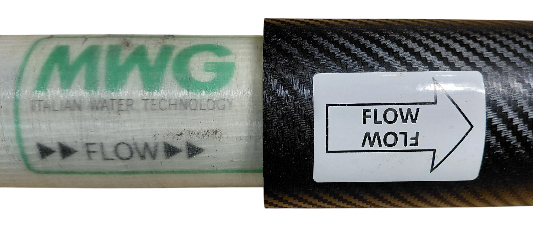
Slide the membrane carefully into the vessel and push it steadily toward the already installed brine-side end cap.
Continue until the membrane’s permeate tube engages fully with the internal O-ring inside the brine-side end cap.
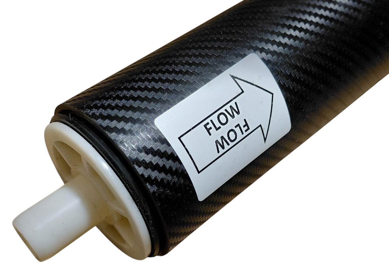
🔒 10. Install the Feed-Side End Cap
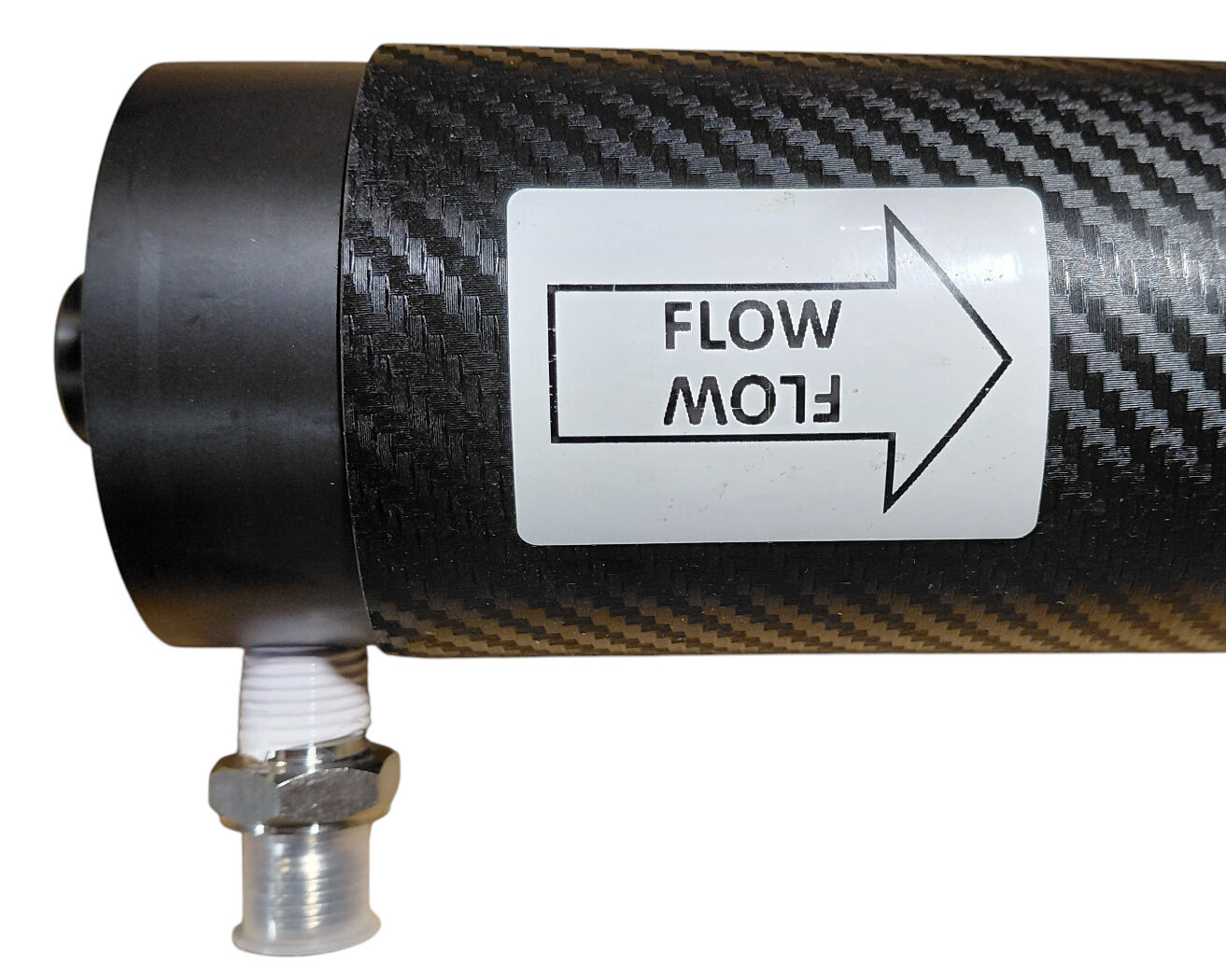
Prepare the feed-side end cap in exactly the same way as the brine-side cap:
- Confirm that the two external O-rings are correctly seated.
- Confirm that the internal permeate-tube O-ring is installed.
- Apply a light film of silicone grease to all O-rings.
- Lubricate the internal wall at the feed end of the tube.
Align the central bore of the end cap with the membrane’s permeate tube and insert the cap squarely into the vessel.
Push it inward until it is correctly and evenly seated.
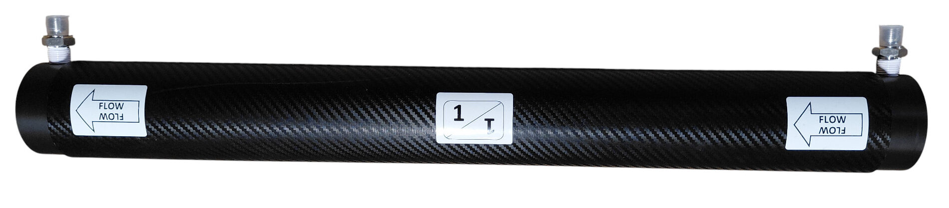
🧱 11. Position the Aluminium Closure Plates
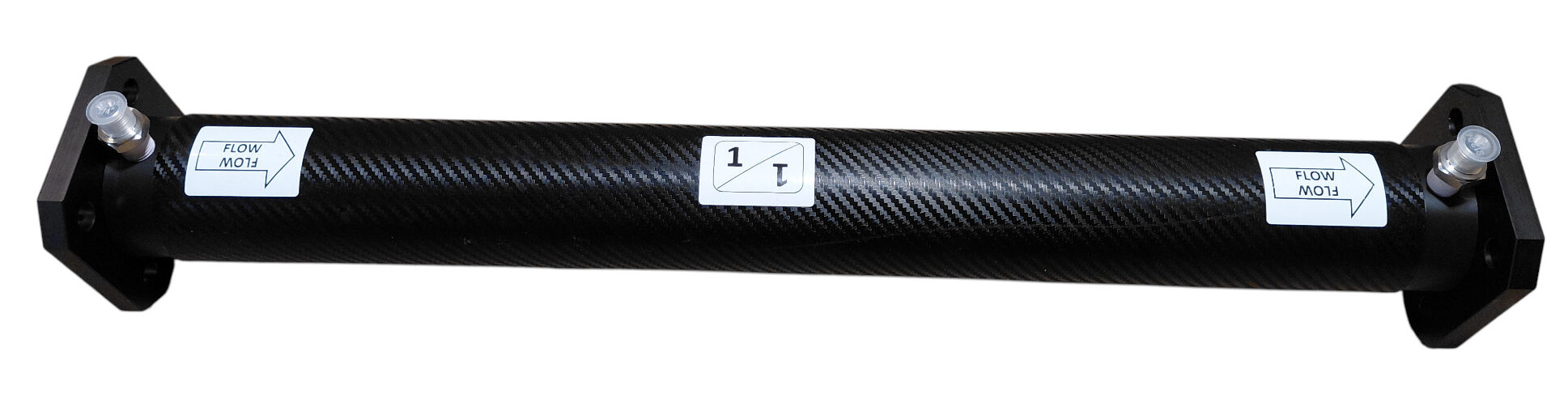
Place one aluminium closure plate at each end of the assembled vessel.
The plates retain the end caps and distribute the axial load generated when the vessel is pressurised.
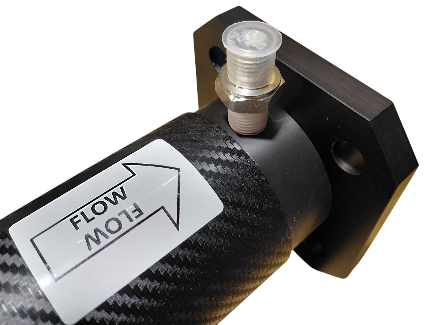
Check that:
- Both plates are correctly centred.
- The high-pressure fittings pass through the appropriate openings without interference.
- The plates sit flat against the ends of the assembly.
- No hose fitting or permeate connection is trapped behind a plate.
🔗 12. Install the Tie Rods
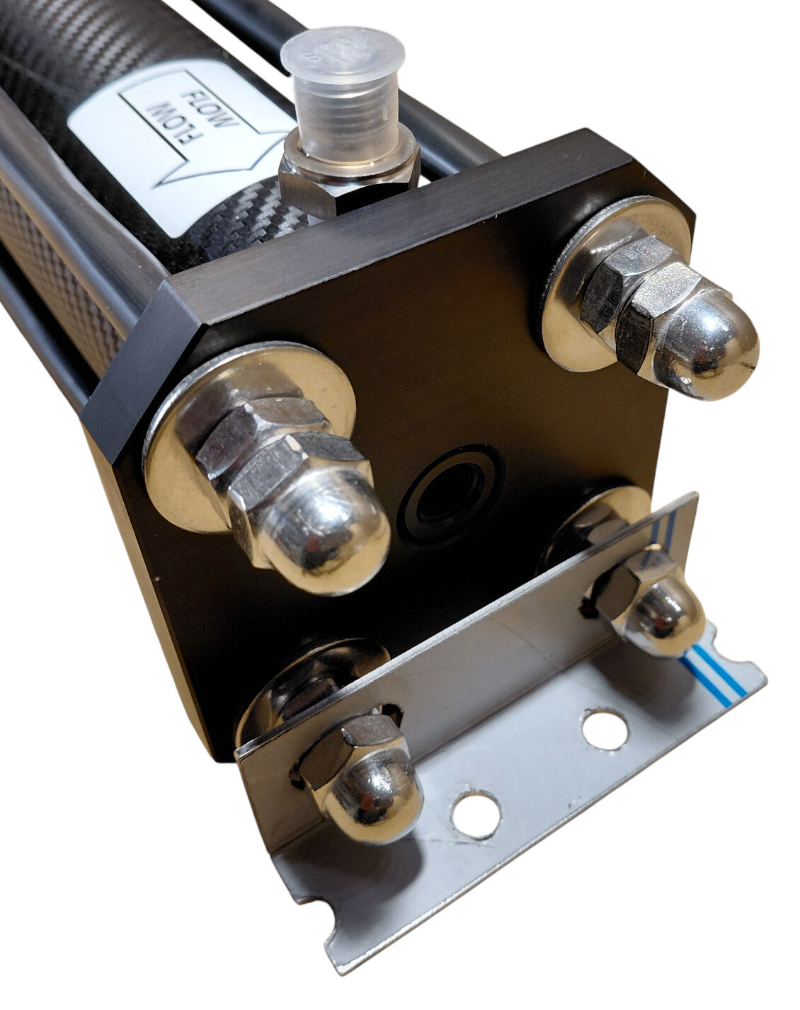
Pass the four PVC-coated stainless-steel tie rods through the corresponding holes in both closure plates.
Fit the large 10 × 30 mm stainless-steel washers and the standard M10 nuts on both ends.
Tighten the nuts progressively and evenly:
- Bring all nuts into light contact.
- Check that both plates remain parallel.
- Tighten opposite rods alternately.
- Continue gradually until the assembly is firm and evenly compressed.
🧲 13. Install the Mounting Brackets and Cap Nuts
Once the standard nuts have been tightened and the vessel assembly is stable, position the two stainless-steel mounting brackets on the tie rods.
Install the stainless-steel M10 cap nuts on both ends and tighten them to secure the brackets and finish the retaining assembly.
Confirm that:
- The brackets are aligned with the intended mounting surface.
- The closure plates remain parallel.
- The tie rods are not visibly bent.
- The end caps remain centred in the pressure tube.
🚰 14. Install the Product-Water Connector and Plug
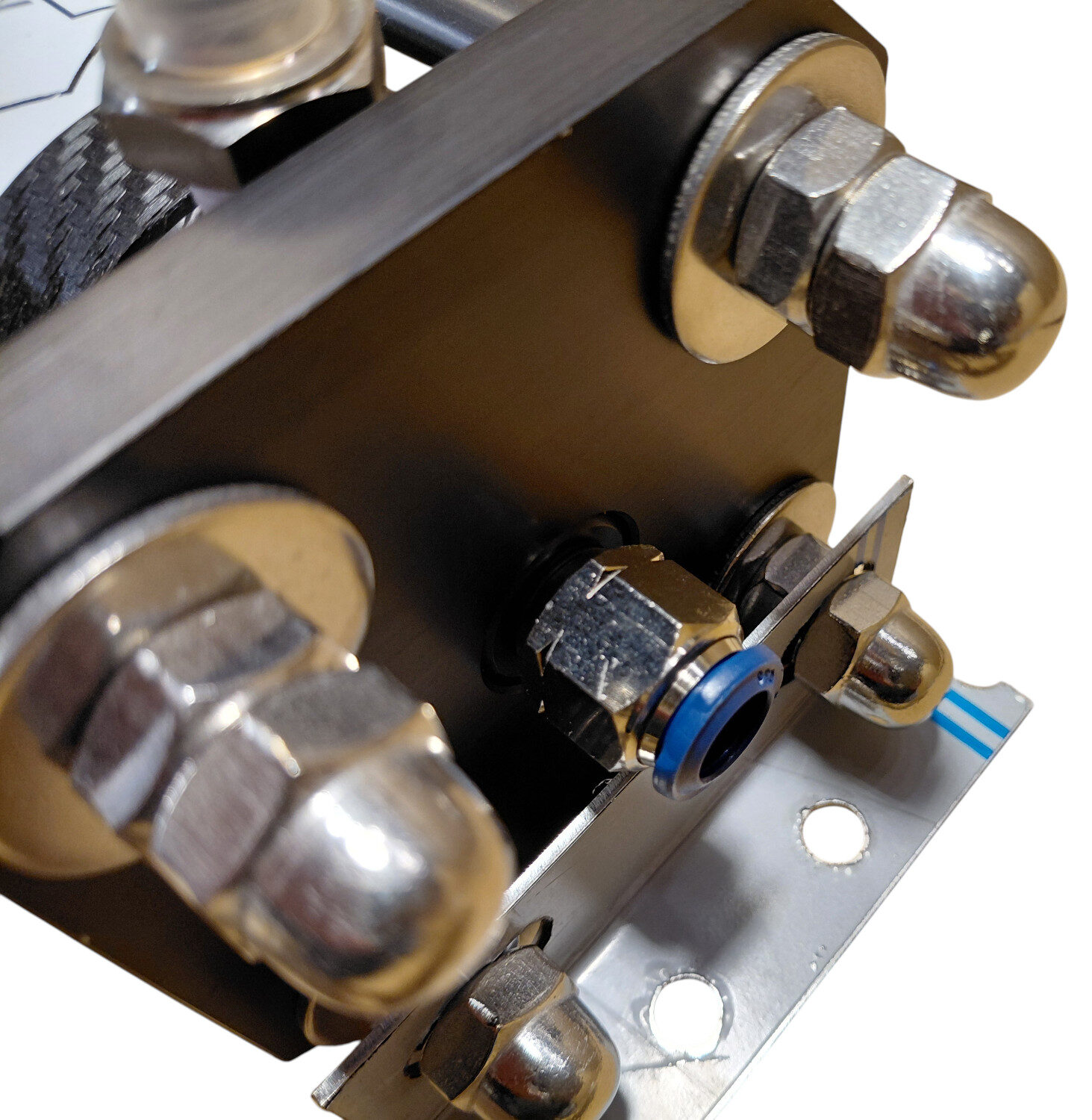
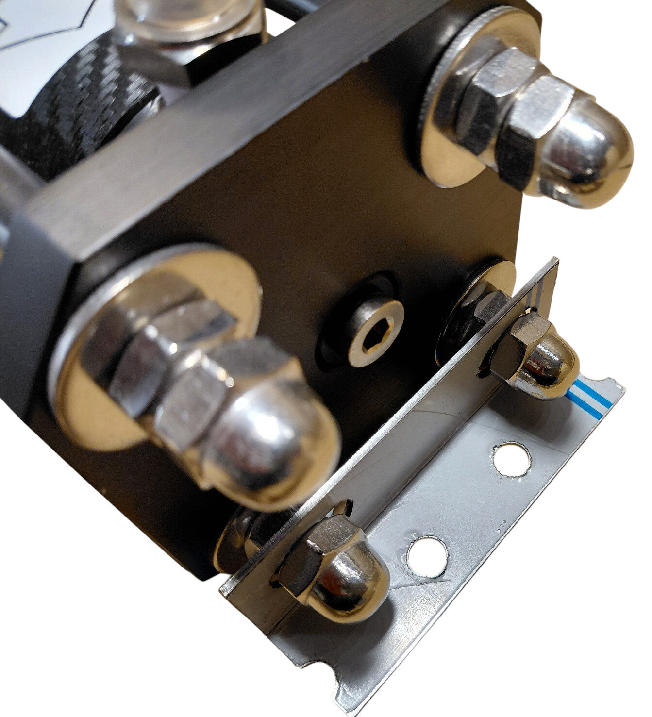
The central product-water passage can normally be accessed from either end of the vessel.
Install the ¼-inch John Guest push-fit connector on the selected permeate outlet and install the supplied plug on the opposite end.
- Inspect the small sealing O-rings on both fittings.
- Apply a very light film of silicone grease to the O-rings.
- Insert or screw the fittings into their respective permeate ports according to their design.
- Confirm that both fittings are fully seated.
🏷️ 15. Apply the Identification Labels
After final assembly, clean the outside of the pressure tube and apply the supplied labels.
The labels should clearly identify:
- The seawater flow direction.
- The feed end.
- The brine end.
- The product-water connection where appropriate.
🛠️ 16. The Vessel Must Be Securely Mounted
Before the pressure vessel is connected and pressurised, it must be fixed securely to a rigid onboard surface using the two supplied stainless-steel brackets.
The mounting is not merely intended to prevent the vessel from moving around the compartment. It also helps maintain the geometry of the complete closure assembly.
Repeated pressure cycles create axial and mechanical loads that can alter the alignment of the closure plates, tie rods and end caps if the assembly is allowed to move or flex.
Secure mounting is especially important in multi-membrane assemblies, where the vessel group is longer, heavier and subject to greater cumulative movement.
🔄 17. Multi-Membrane Vessel Connections
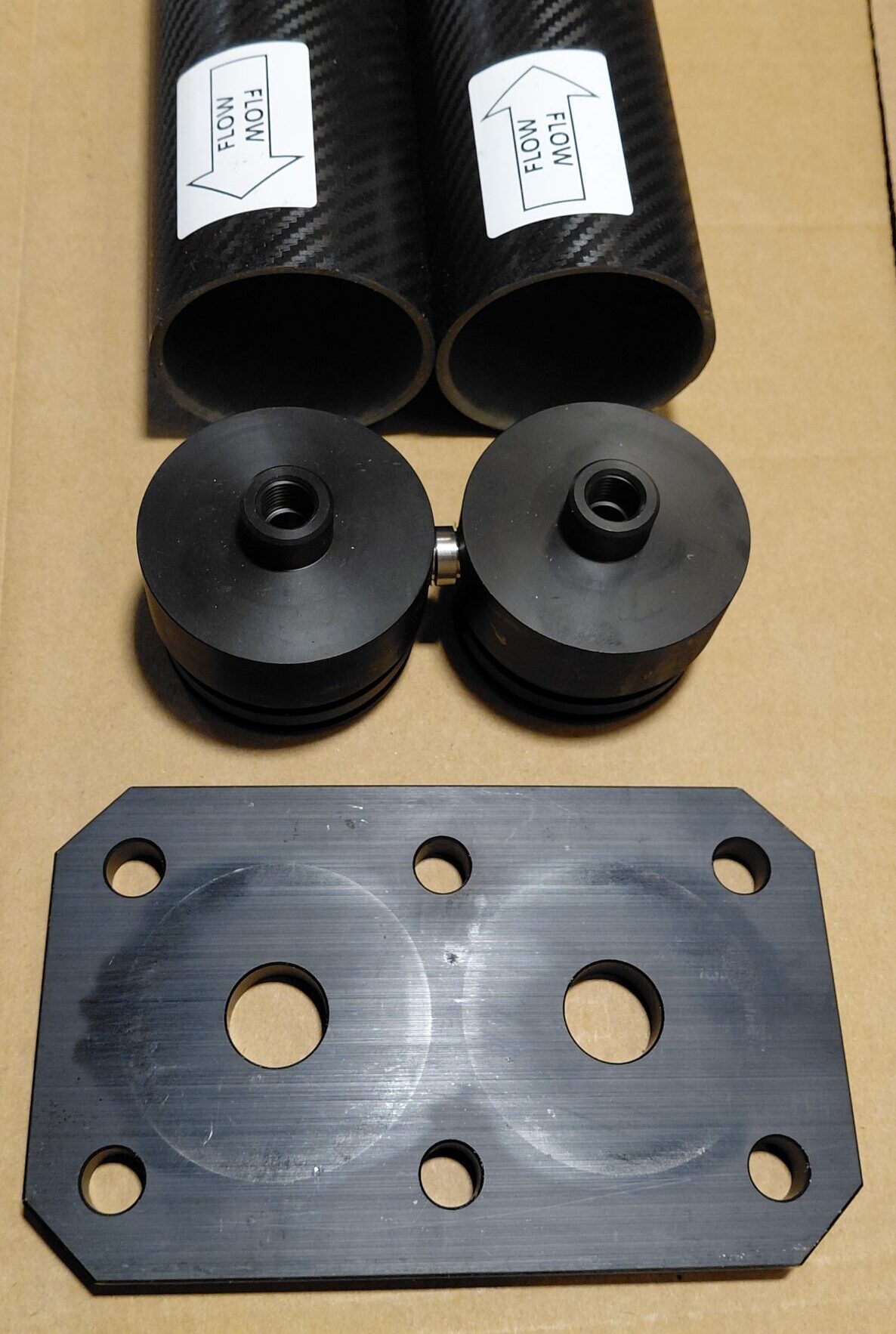
In a multi-membrane BlueGold arrangement, two adjacent vessels can be connected directly through a dedicated interconnector nipple fitted with O-rings.
This eliminates the need for an external high-pressure hose between the two intermediate end caps.
Intermediate Connection
- The intermediate end caps do not use the standard threaded high-pressure nipple.
- Each cap contains a smooth receiving bore for the interconnector.
- The interconnector O-rings seal directly inside these bores.
- A dedicated double closure plate retains the two vessel ends together.
Assembly Procedure
- Inspect the interconnector and its O-rings.
- Apply a light film of silicone grease to the O-rings.
- Lightly lubricate the receiving bores in both intermediate end caps.
- Insert the interconnector into one cap.
- Align and bring the second vessel into position.
- Confirm that the nipple enters both caps without pinching an O-ring.
- Install the dedicated double closure plate.
- Fit and tighten the complete tie-rod system evenly.
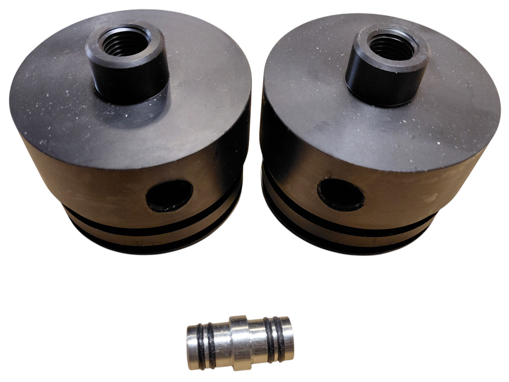
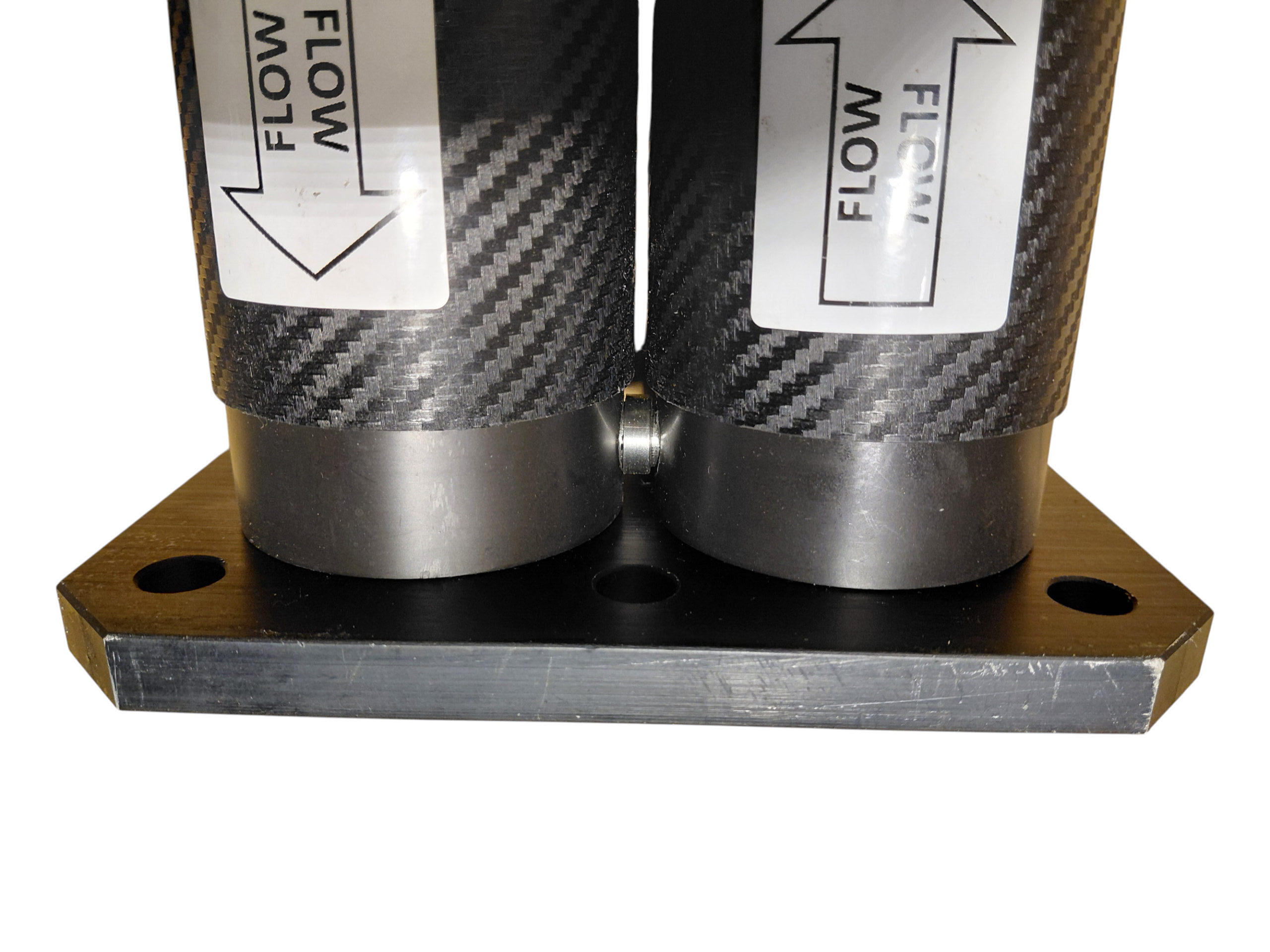
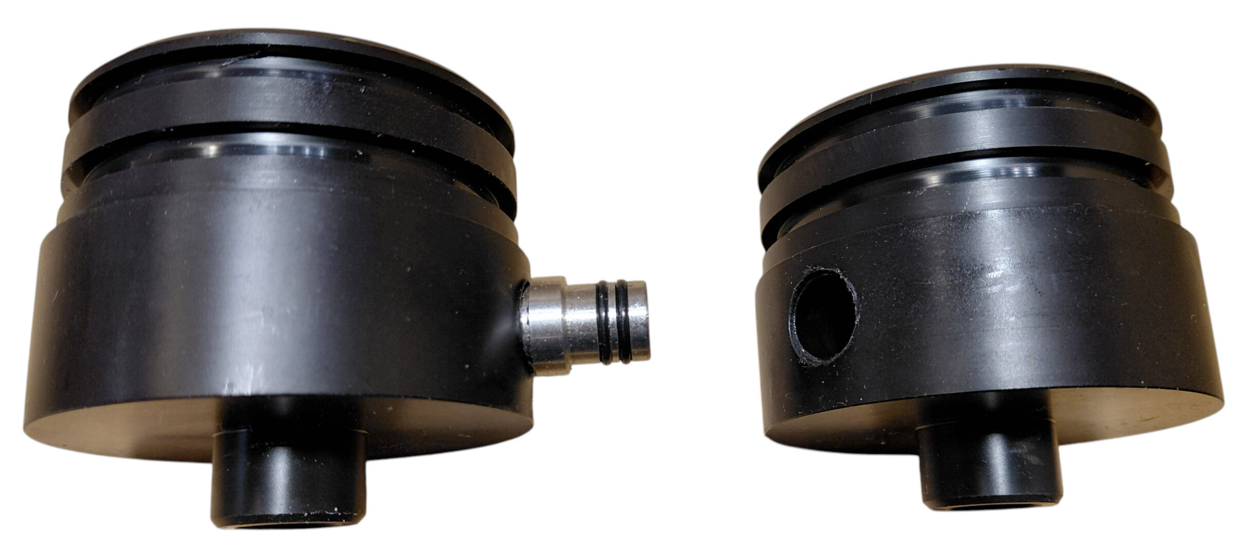
A double-vessel assembly normally uses six tie rods instead of four. The number of washers, standard nuts and cap nuts increases accordingly.
⚠️ 18. The Three Fundamental Assembly Rules
| Rule | Why it matters |
|---|---|
| Install the brine-side end cap first | It provides the fixed receiving point for the membrane’s permeate tube during insertion. |
| Insert the membrane from the feed side in the marked flow direction | The membrane brine seal and internal flow path are directional. |
| Secure the complete assembly before pressurising it | Rigid mounting preserves alignment and prevents movement during repeated pressure cycles. |
🔍 19. Final Inspection Before Installation
Before connecting the vessel to the watermaker, verify the following:
- The membrane flow direction matches the vessel flow labels.
- The brine-side end cap was installed before the membrane.
- The membrane was inserted from the feed side.
- All external and internal O-rings were installed and lubricated.
- The end caps are fully and evenly seated.
- The closure plates are parallel.
- All tie rods are straight and evenly tightened.
- The mounting brackets are firmly secured.
- The NPT fittings are sealed without excessive tightening.
- The permeate connector and plug are correctly installed.
- No PTFE tape has been used on O-ring-sealed connections.
- The complete vessel is securely mounted before pressure testing.
💧 20. Initial Pressure Test
The first pressurisation should be carried out gradually while every end-cap, high-pressure and permeate connection is observed.
- Establish stable low-pressure feed-water flow.
- Confirm that the vessel is completely flooded and free of trapped air.
- Inspect all low-pressure connections.
- Start the high-pressure pump with the regulating valve open.
- Increase pressure slowly.
- Check both end caps, high-pressure nipples and permeate fittings for leakage.
- Stop immediately if any component shifts, leaks or becomes misaligned.
Install the brine end cap first, follow the membrane’s flow direction, protect every O-ring with light silicone lubrication, tighten the retaining structure evenly and always secure the complete assembly before applying pressure.
The BlueGold 3-inch pressure vessel performs the same basic function as the 2.5-inch version, but its construction is different. The end caps, retaining plates, hydraulic inserts and membrane spacers are specific to the 3-inch design, so the assembly procedure must be followed separately.
This guide describes the components and assembly sequence of the BlueGold 3-inch pressure vessel for a standard 3021 seawater reverse osmosis membrane.
Install the brine-side end cap first → insert the membrane from the feed side in the correct flow direction → install the feed-side end cap last.
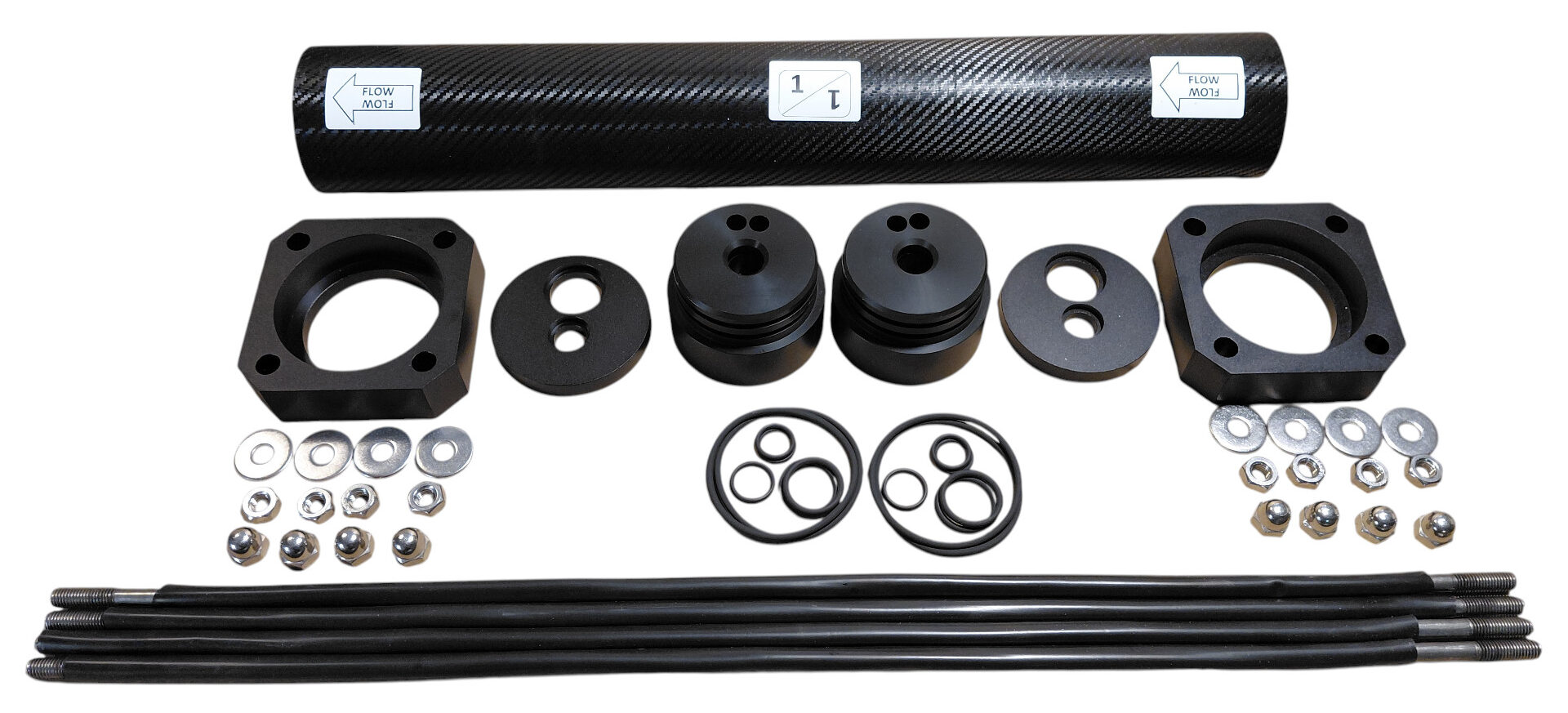
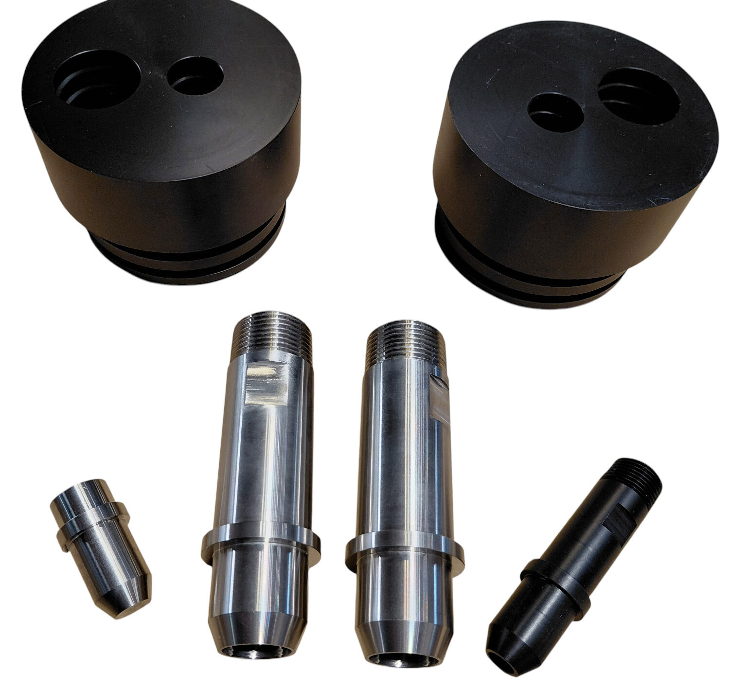
📦 1. Components Included
A standard BlueGold 3-inch pressure-vessel assembly includes:
- 1 pressure tube: 21-inch length for a 3021 seawater membrane.
- 2 Delrin end caps: One for the feed end and one for the brine end.
- 2 round closure plates: These retain the feed, brine and permeate inserts inside the end caps.
- 2 square closure plates: These secure the complete end-cap assemblies to the pressure tube.
- 4 large external O-rings: Two for each end cap, sealing against the internal wall of the pressure tube.
- 2 internal membrane O-rings: These seal the membrane permeate tube inside the end caps.
- 4 O-rings for the ¾-inch feed and brine inserts.
- 4 O-rings for the ¼-inch permeate insert and permeate plug.
- 2 plastic membrane spacers: One fitted at each end of the membrane.
- 2 AISI 316L stainless-steel inserts: One for feed and one for brine.
- 1 Delrin ¼-inch permeate insert.
- 1 permeate-side plug.
- 4 stainless-steel tie rods with protective PVC coating.
- 8 stainless-steel washers, 10 × 30 mm.
- 8 stainless-steel M10 nuts.
- 8 stainless-steel M10 cap nuts.
- 1 set of identification and flow-direction labels.
🧰 2. Tools and Materials Required
- Suitable spanners for the M10 nuts
- Clean silicone grease compatible with membrane and potable-water applications
- Clean lint-free cloth
- Marker for temporary flow-direction identification
- Anaerobic thread sealant for the high-pressure fittings
- PTFE tape for the permeate fitting only
➡️ 3. Mark the Flow Direction
Before installing any internal component, identify the intended feed and brine ends of the pressure tube.
Mark the seawater flow direction temporarily on the outside of the tube:
The permanent labels supplied with the vessel can be applied after final assembly.
⭕ 4. Prepare Both End Caps
Before inserting either end cap into the pressure tube, install all the required O-rings in their correct grooves.
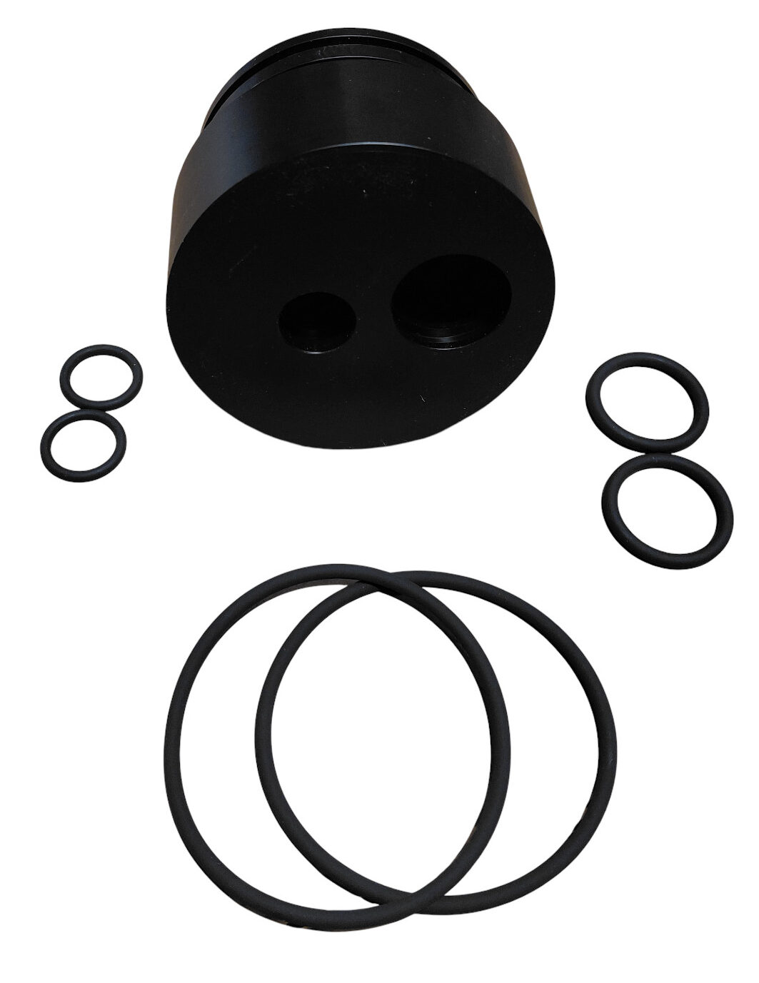
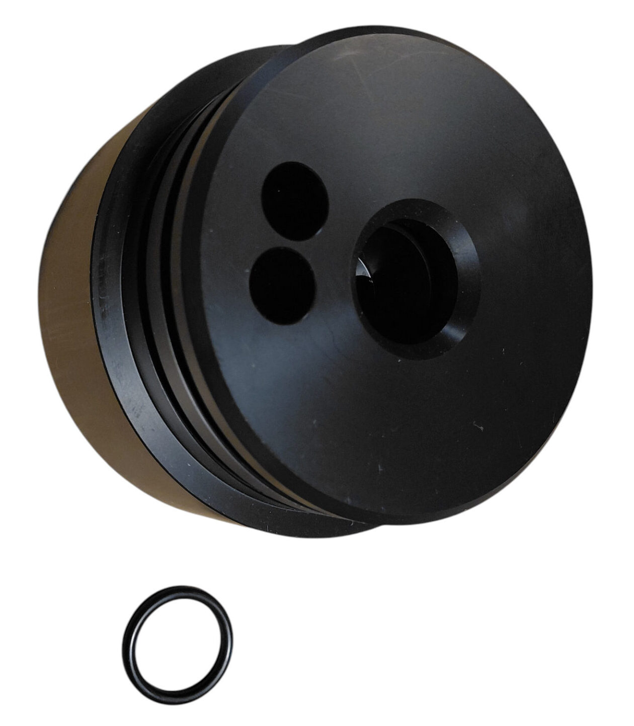
For Each End Cap
- Install the two large external O-rings around the outside of the cap.
- Install the internal O-ring that seals around the membrane permeate tube.
- Install the two O-rings for the ¾-inch feed or brine insert.
- Install the two O-rings for the permeate insert or permeate plug.
Check carefully that every O-ring:
- Sits completely inside its groove.
- Is not twisted.
- Is not stretched or pinched.
- Is free from dirt, cuts or flattening.
🧴 5. Lubricate Only the Seals Needed for End-Cap Insertion
At this stage, apply a light film of silicone grease to:
- The two large external O-rings on the brine-side end cap.
- The internal membrane O-ring on the brine-side end cap.
- The internal wall of the pressure tube near the brine end.
Do not yet lubricate the O-rings for the feed, brine, permeate insert or plug. These will be lubricated immediately before those components are installed later.
🚿 6. Install the Brine-Side End Cap First
Identify the end of the pressure tube marked as the brine outlet.
Align the prepared brine-side end cap with the tube and press it inward evenly.
Because the 3-inch vessel uses large external O-rings and a close mechanical fit, some firm hand pressure may be required.
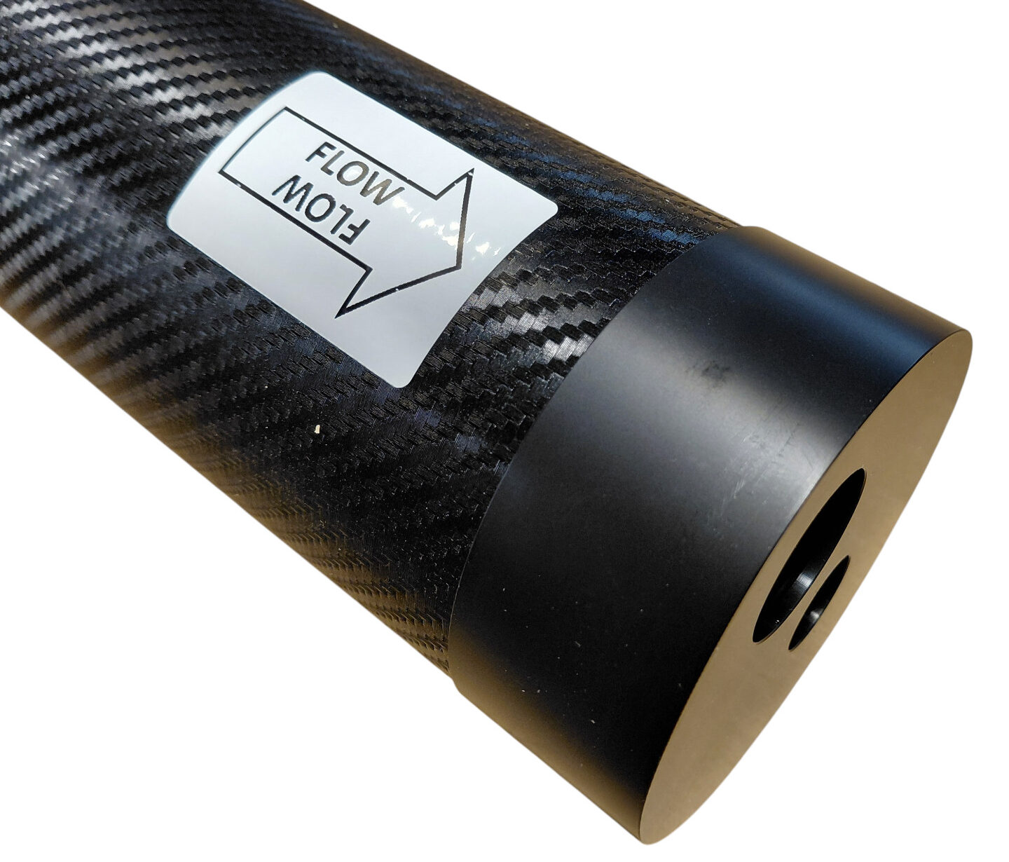
If the cap does not enter evenly:
- Remove it.
- Inspect the O-rings.
- Confirm that the grooves and vessel wall are clean.
- Apply a little more silicone grease if necessary.
- Try again with the cap correctly aligned.
🧬 7. Prepare the 3021 Membrane
Before inserting the membrane, inspect it carefully.
Confirm that:
- The membrane is the correct 3021 format.
- The external wrapper is undamaged.
- The central permeate tube is clean.
- The membrane seal is correctly seated.
- The flow-direction arrow is clearly visible.
Install the Plastic Membrane Spacers
Fit one supplied plastic spacer at each end of the membrane before insertion.
These spacers position the membrane correctly between the two end caps and maintain the intended internal geometry of the assembled vessel.
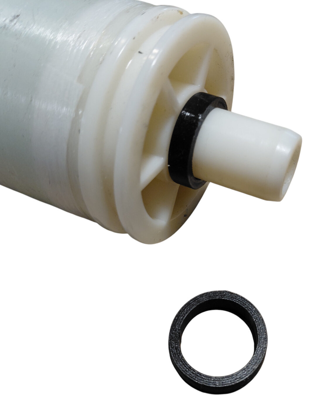
🧴 8. Lubricate the Membrane and Feed-Side Tube Entrance
Apply a light film of silicone grease to:
- The membrane seal.
- Both ends of the membrane permeate tube.
- The internal wall of the open feed end of the pressure tube.
➡️ 9. Insert the Membrane from the Feed Side
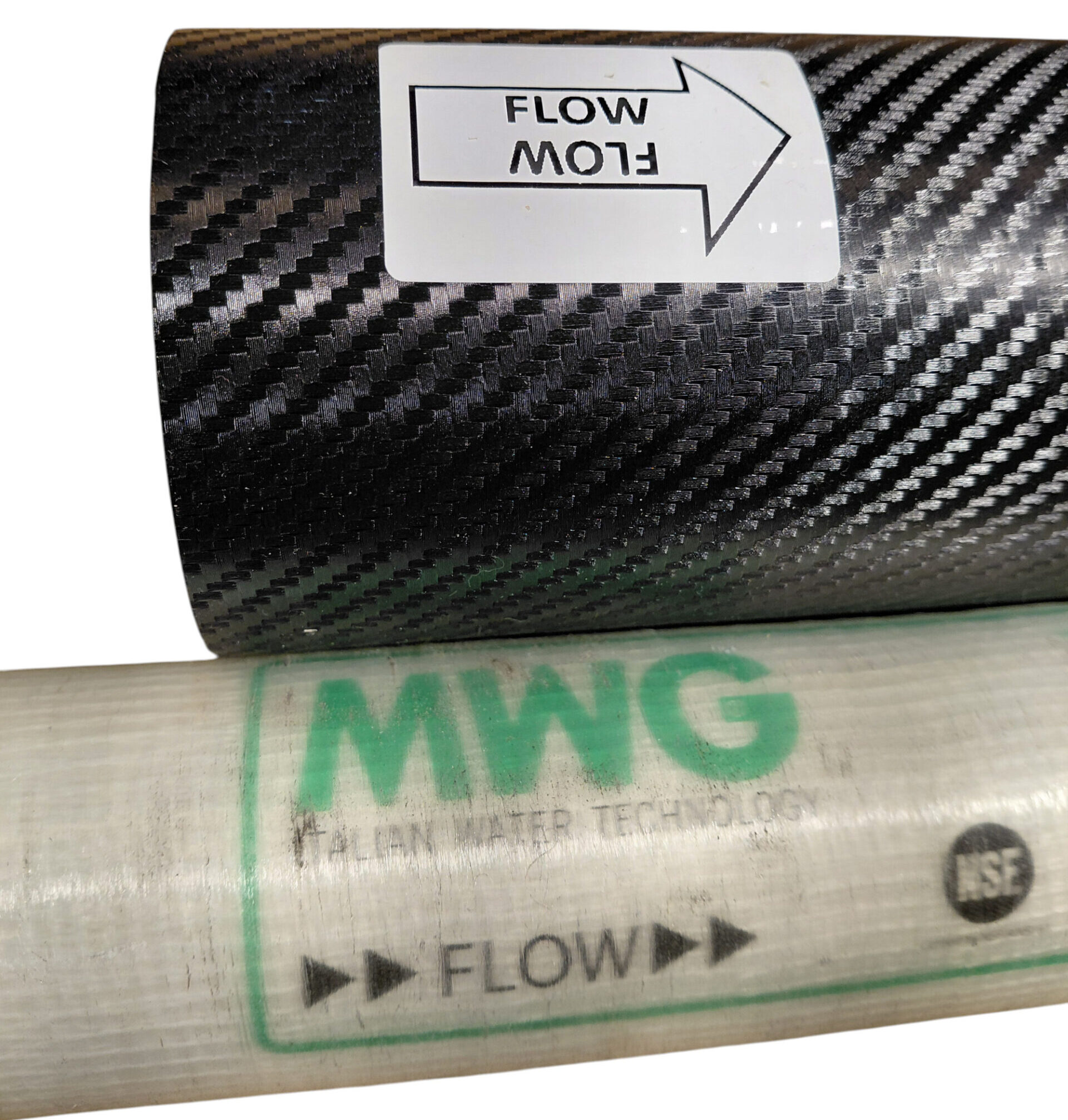
Insert the membrane from the end of the tube that has remained open: the feed side.
The arrow printed on the membrane must point in the same direction as the flow arrow marked on the vessel.
Slide the membrane carefully into the tube and push it steadily toward the already installed brine-side end cap.
Continue until the membrane permeate tube engages fully with the internal O-ring in the brine-side end cap and the spacer reaches its correct position.
🔒 10. Install the Feed-Side End Cap
Prepare the feed-side end cap in the same way as the brine-side cap.
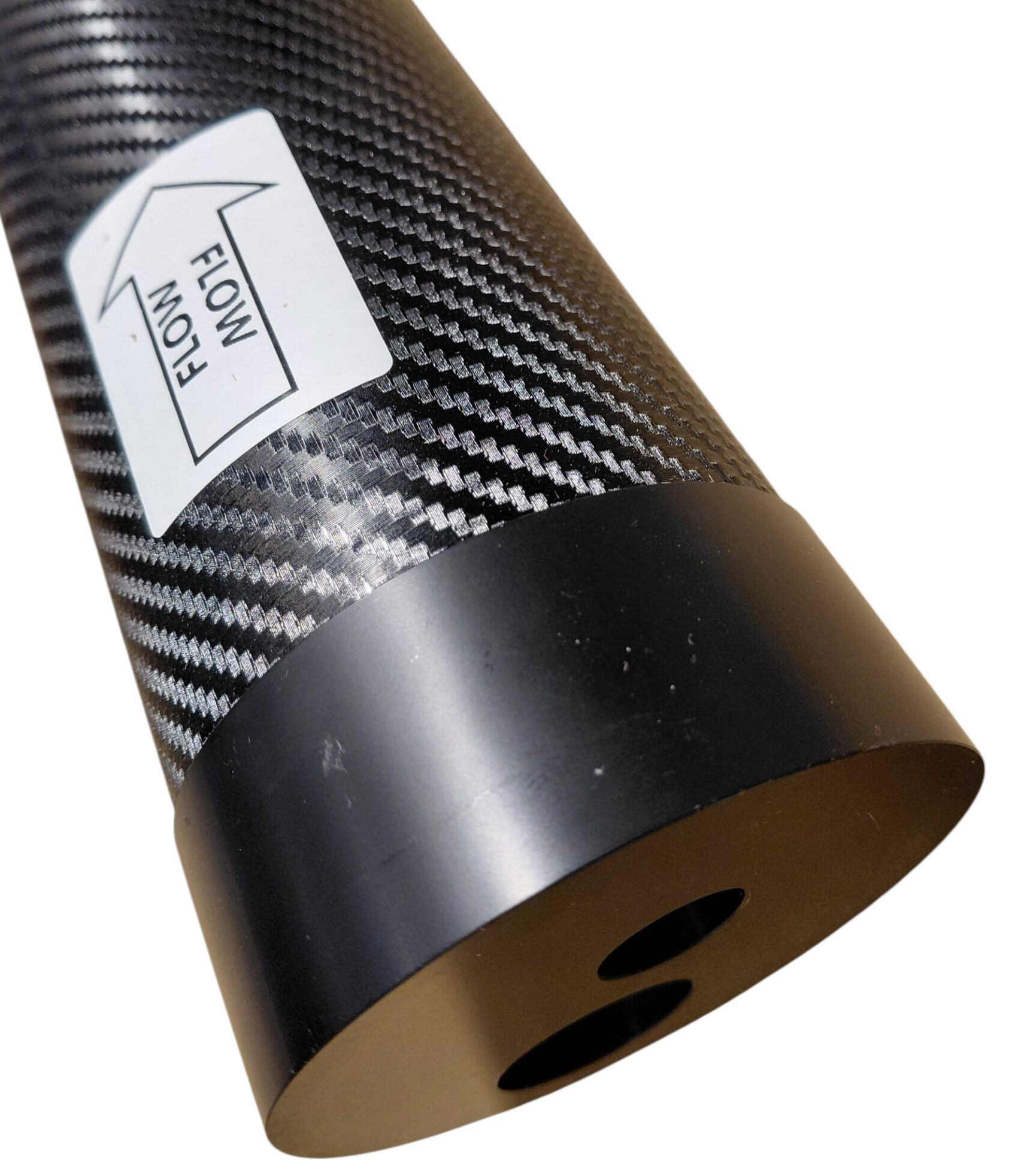
Apply a light film of silicone grease to:
- The two large external O-rings.
- The internal membrane O-ring.
- The internal wall of the tube near the feed end.
Align the end cap with the membrane permeate tube and press it into the vessel squarely and evenly.
Some firm pressure may again be required because of the large external O-rings.
🔩 11. Install the Feed, Brine and Permeate Inserts
The 3-inch vessel uses separate removable inserts for the feed, brine and permeate connections.
Before installing them, apply a light film of silicone grease to:
- All insert O-rings.
- The conical sealing surfaces of the inserts.
- The corresponding bores in the Delrin end caps.
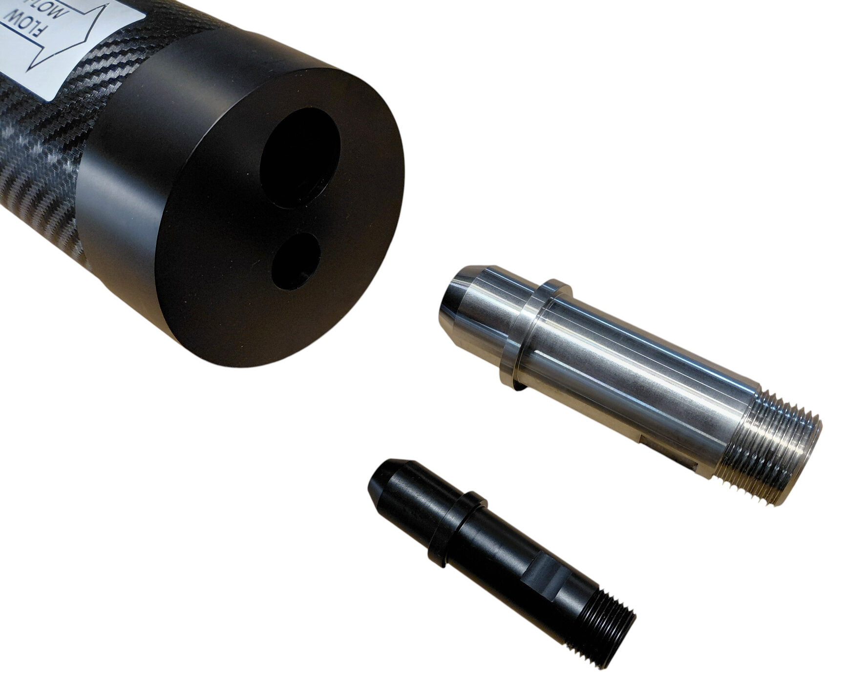
Feed and Brine Inserts
Insert the two AISI 316L stainless-steel ¾-inch components into the designated feed and brine ports.
Push each insert straight into its bore until it is fully seated.
Permeate Insert and Plug
Install the Delrin ¼-inch permeate insert at the selected product-water outlet and install the permeate plug at the opposite end.
Again, press both components into their bores until they are fully and evenly seated.
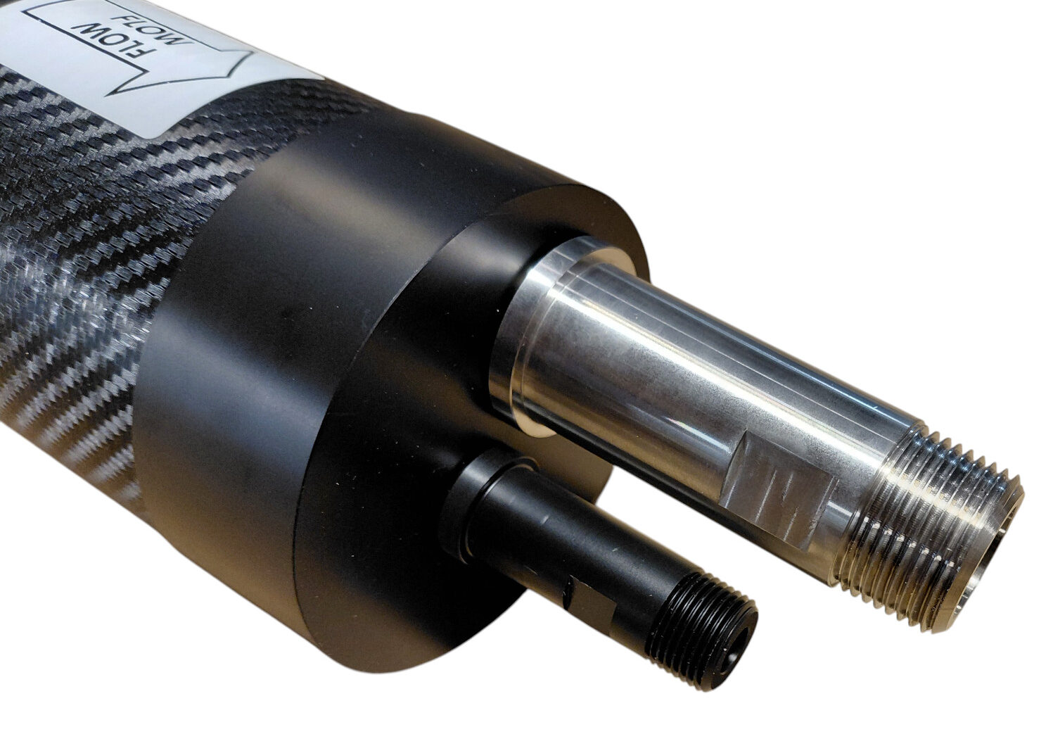
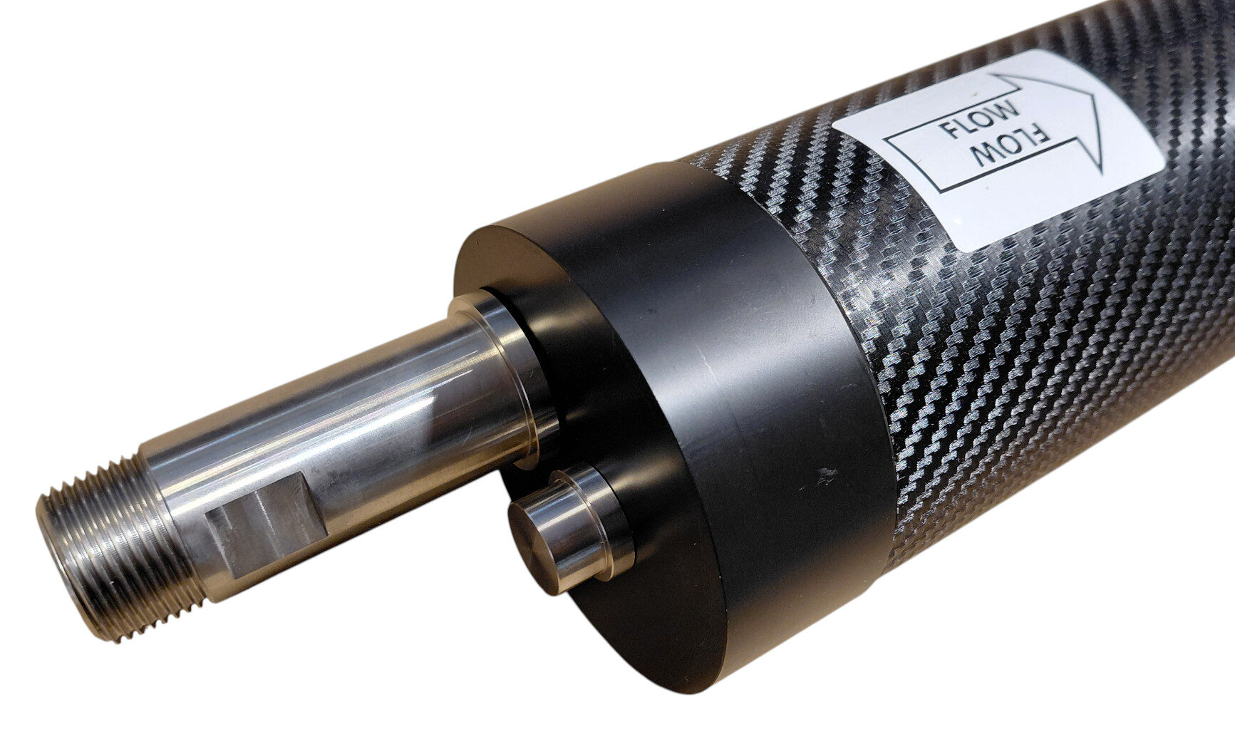
⭕ 12. Install the Round Retaining Plates
Place one round closure plate over each end-cap assembly.
The round plates directly retain the feed, brine and permeate inserts inside their respective bores.
Check that:
- Each insert passes correctly through its designated opening.
- The plate sits flat against the end cap.
- No insert is tilted or trapped.
- The permeate plug and connector remain fully seated.
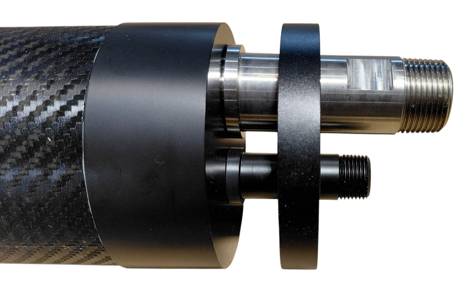
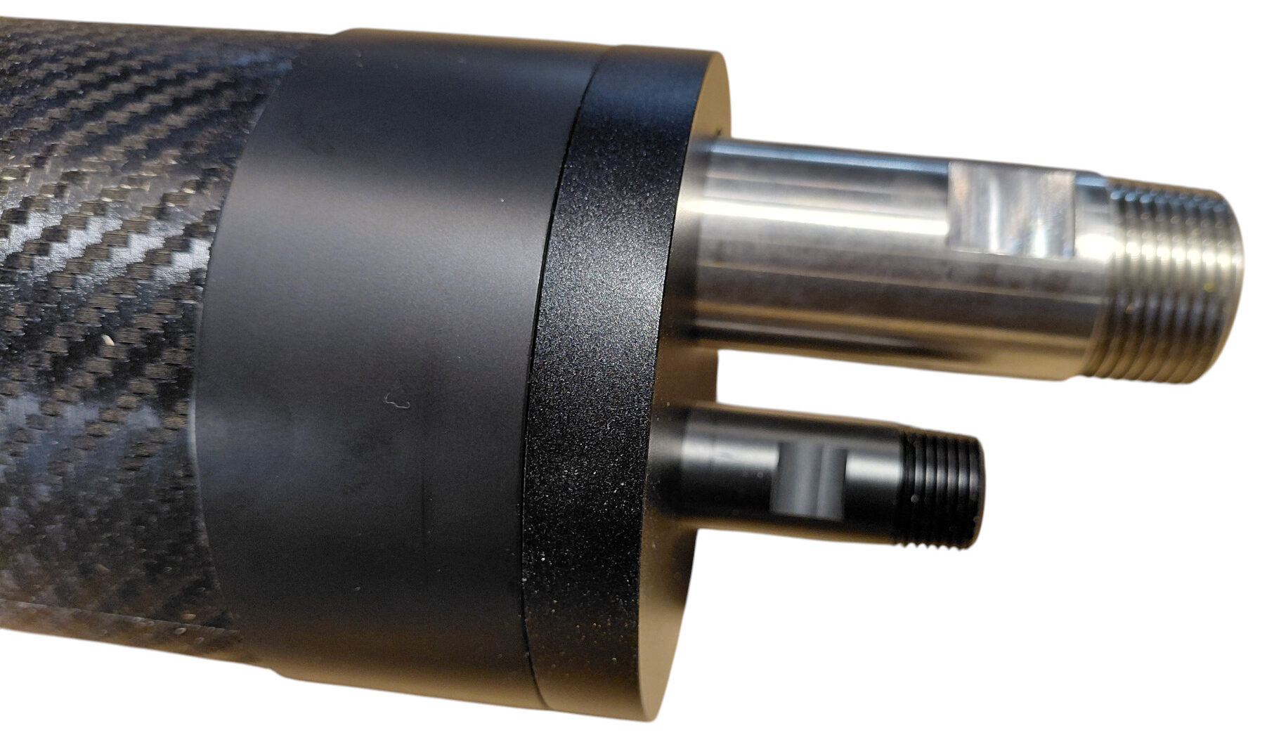
⬛ 13. Install the Square Closure Plates
Position one square closure plate outside each round retaining plate.
The square plates form the structural ends of the complete assembly and transfer the axial pressure load to the tie rods.
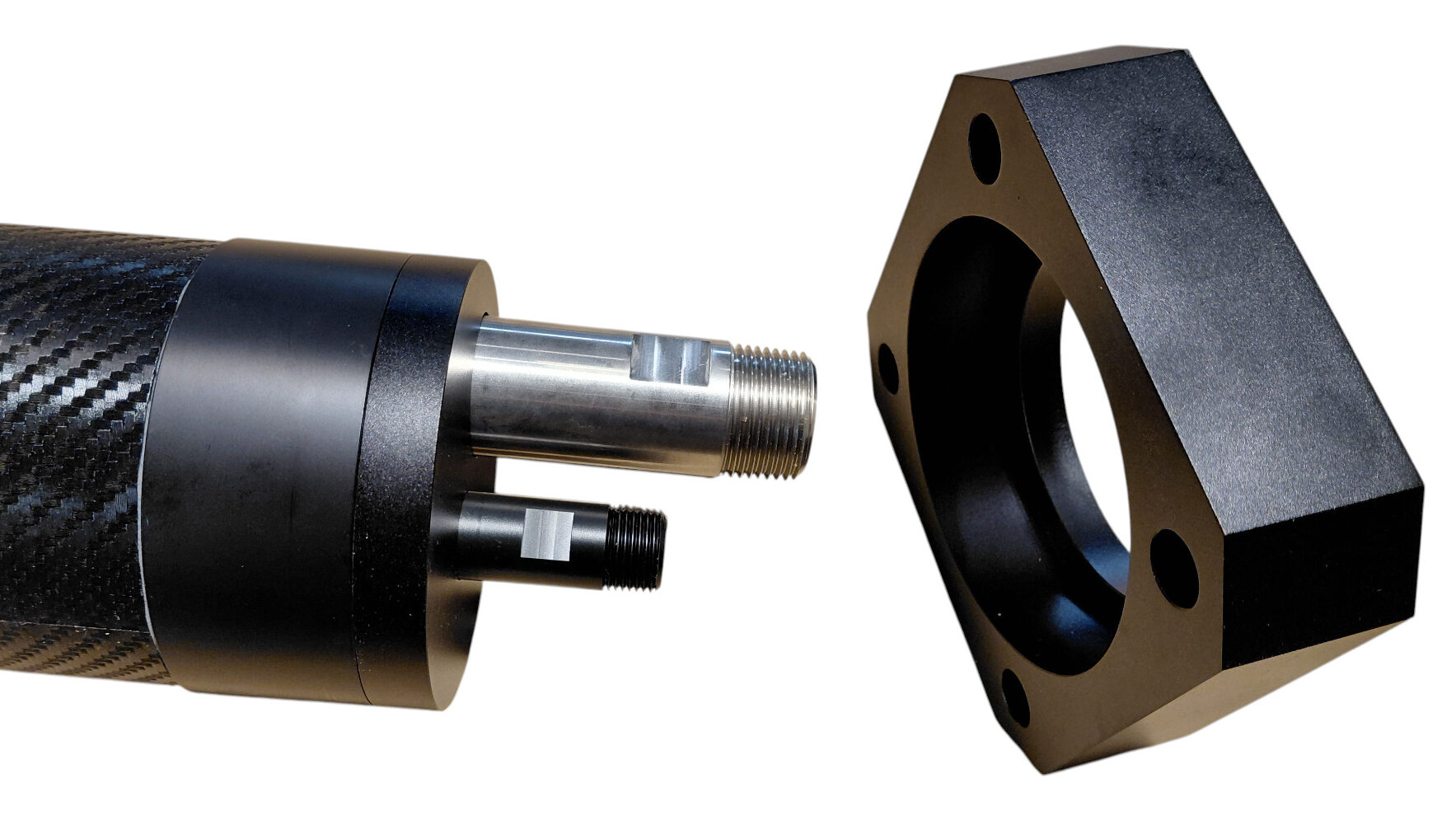
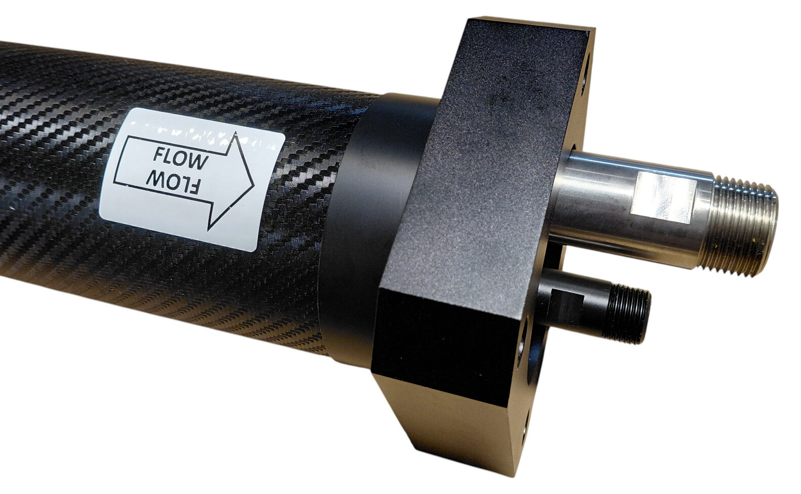
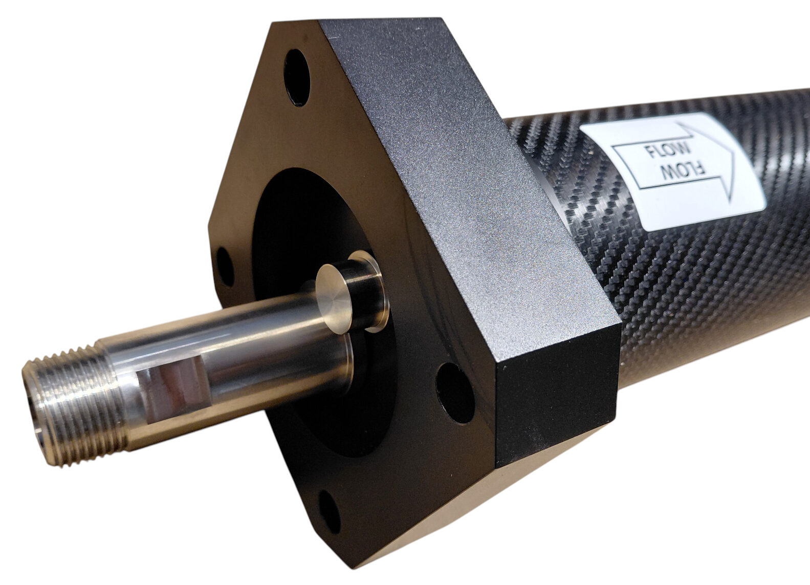
Confirm that:
- The square plate is centred on the vessel.
- The four tie-rod holes align correctly.
- The round plate remains flat behind it.
- The hydraulic inserts remain correctly seated.
🔗 14. Install and Tighten the Tie Rods
Pass the four PVC-coated stainless-steel tie rods through the aligned holes in both square closure plates.
Fit the 10 × 30 mm stainless-steel washers and standard M10 nuts on both ends.
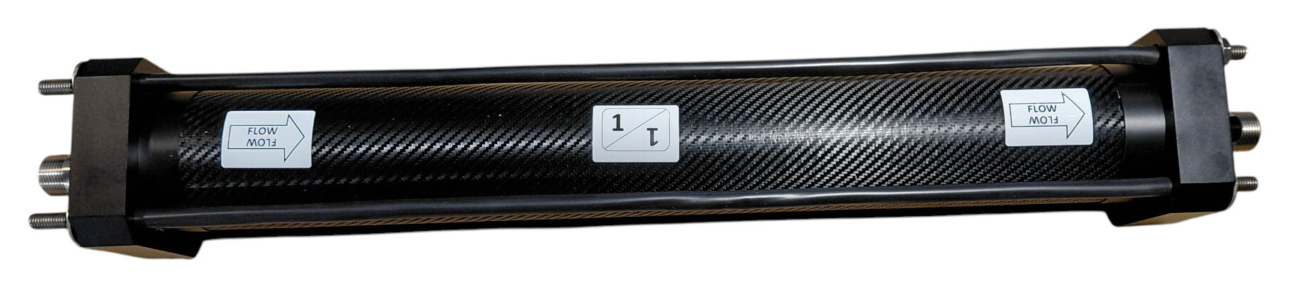
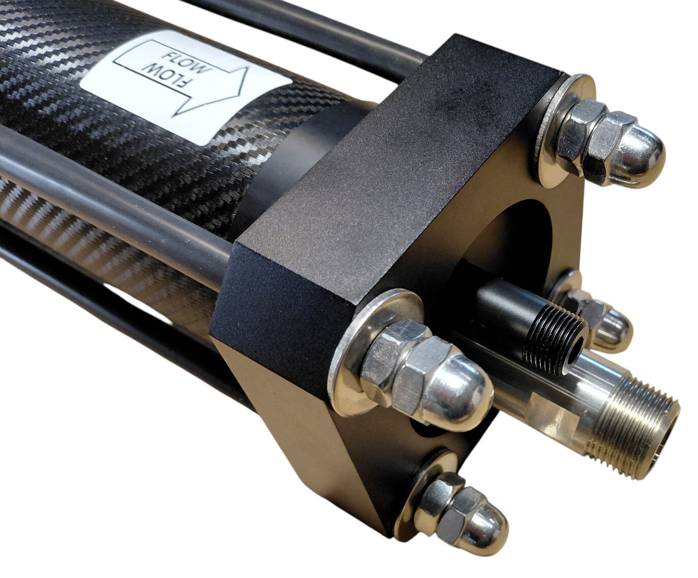
Recommended Tightening Sequence
- Bring all nuts into light contact.
- Confirm that both square plates are parallel.
- Tighten diagonally opposite rods in sequence.
- Increase tension gradually and uniformly.
- Check repeatedly that the plates and end caps remain centred.
🔘 15. Install the Cap Nuts
Once the standard M10 nuts have been tightened and the vessel geometry has been checked, install the stainless-steel M10 cap nuts on all tie-rod ends.
The cap nuts provide a finished external surface and protect the exposed tie-rod threads.
Complete a final visual check to confirm that:
- Both square plates remain parallel.
- The round plates remain correctly trapped behind them.
- The inserts are centred and fully retained.
- The tie rods are straight.
- No end-cap O-ring is visibly extruded.
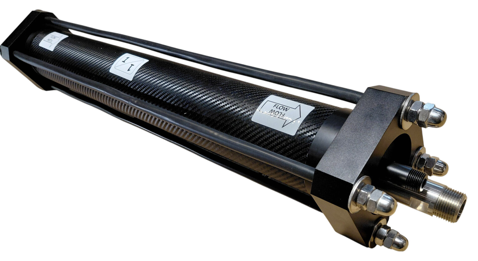
🏷️ 16. Apply the Identification Labels
Clean the outer surface of the vessel and apply the supplied labels after assembly.
The labels should clearly indicate:
- The seawater flow direction.
- The feed connection.
- The brine connection.
- The product-water connection where appropriate.
- The 3021 membrane format.
🛠️ 17. Mounting Hardware and Hydraulic Fittings
The standard BlueGold 3-inch pressure-vessel kit does not include mounting brackets or the final external hydraulic fittings.
These items should be selected separately according to the layout and hose system used onboard.
Possible mounting and connection options may include:
- Dedicated vessel clamps or saddles.
- Custom brackets fixed to a rigid bulkhead or equipment frame.
- Flexible high-pressure hoses.
- Stainless-steel elbows or straight fittings.
- Adapters suitable for the selected feed, brine and permeate hose sizes.
🚫 18. Never Lift the Vessel by the Inserts
Do not lift, carry, rotate or position the assembled pressure vessel by holding the feed, brine or permeate inserts.
These parts are designed to provide hydraulic connections and to be retained by the closure plates. They are not handles or structural lifting points.
Loading the inserts sideways can damage O-rings, distort the receiving bores or create future leaks.
🧪 19. Install the External Hydraulic Fittings Only After Vessel Assembly
The final high-pressure fittings should be installed on the stainless-steel feed and brine inserts only after the complete vessel has been assembled and tightened.
This prevents the fittings from interfering with the retaining plates and avoids applying unnecessary leverage to loose inserts during assembly.
Recommended High-Pressure Thread Sealant
For the stainless-steel feed and brine fittings, BlueGold recommends a suitable anaerobic thread-sealing compound.
A highly recommended product is:
An anaerobic compound provides reliable sealing without requiring extreme tightening torque.
Advantages
- Excellent resistance to pressure and vibration.
- Uniform sealing around the threaded connection.
- Reduced need for excessive mechanical torque.
- Lower risk of damaging or twisting the removable inserts.
- No loose PTFE fragments entering the high-pressure circuit.
🚰 20. Seal the Permeate Fitting with PTFE Tape Only
The ¼-inch external fitting connected to the Delrin permeate insert should be sealed using approximately two neat turns of PTFE tape.
Apply the tape only to the male thread and keep the first thread reasonably clear.
Tighten the fitting only enough to obtain a secure and correctly oriented connection. Excessive force can damage the plastic thread or load the insert unnecessarily.
⚠️ 21. The Three Fundamental Assembly Rules
| Rule | Why it matters |
|---|---|
| Install the brine-side end cap first | It provides the fixed receiving point for the membrane permeate tube during insertion. |
| Insert the membrane from the feed side in the marked direction | The membrane seal and internal seawater flow path are directional. |
| Install the feed-side end cap last | It closes and positions the membrane only after the brine end has been established. |
🔍 22. Final Inspection Before Mounting
Before installing the vessel onboard, verify the following:
- The membrane flow arrow matches the vessel flow labels.
- The brine-side end cap was installed first.
- The membrane was inserted from the feed side.
- Both plastic membrane spacers are installed.
- All large external O-rings are correctly seated.
- Both internal membrane O-rings are installed.
- All feed, brine, permeate and plug O-rings are present and lubricated.
- All hydraulic inserts are fully seated.
- The round retaining plates sit flat.
- The square closure plates remain parallel.
- The tie rods are straight and evenly tightened.
- The cap nuts are installed.
- No external hydraulic fitting has distorted an insert.
- The vessel will be mounted securely before pressurisation.
💧 23. Initial Pressure Test
The first pressure test should be carried out only after the vessel has been securely mounted and all hydraulic connections have been completed.
- Establish stable low-pressure feed flow.
- Allow the vessel to fill completely and purge trapped air.
- Inspect the feed, brine and permeate connections at low pressure.
- Start the high-pressure pump with the pressure-regulating valve open.
- Increase pressure gradually.
- Inspect both end-cap areas and every insert for leakage.
- Stop immediately if an insert moves, an O-ring leaks or either closure plate becomes misaligned.
Install every O-ring carefully, fit the brine-side end cap first, insert the membrane with its spacers in the correct flow direction, retain the hydraulic inserts with the round plates, secure the complete assembly with the square plates and tie rods, and never use the inserts as lifting points.
The final filter used in the BlueGold system is an activated carbon filter installed on the freshwater flushing line. Its purpose is to remove any residual chlorine from marina or municipal water before that water reaches the reverse osmosis membranes.
🚿 1. Why Chlorine Must Be Removed
Freshwater supplied from a marina or municipal network may contain chlorine or chloramine used for disinfection.
Although these substances are useful in a drinking-water distribution network, oxidising disinfectants can damage seawater reverse osmosis membranes.
Repeated exposure may reduce salt rejection and shorten membrane life. The damage may be gradual and is normally irreversible.
Before shore water is used for flushing, any residual oxidising disinfectant should be removed.
🧱 2. How the Activated Carbon Filter Works
Activated carbon has a highly porous internal structure. As flushing water passes through the cartridge, residual chlorine is removed before the water enters the watermaker.
The filter is installed only in the freshwater flushing circuit:
Its purpose is membrane protection, not the treatment of seawater or newly produced product water.
📍 3. Correct Installation Position
The carbon filter should be installed upstream of the flushing solenoid valve or manual three-way valve, so that all freshwater used for flushing passes through it.
The housing should remain accessible for cartridge replacement and should be installed with the correct flow direction where indicated.
🔄 4. Cartridge Replacement
Activated carbon has a limited chlorine-removal capacity. Once the medium is exhausted, water may still pass through the cartridge even though chlorine is no longer being removed effectively.
Replacement frequency depends on:
- The quantity of flushing water used.
- The chlorine concentration in the freshwater supply.
- The cartridge size and carbon quality.
- The time the cartridge has remained wet and unused.
Replace the cartridge periodically and whenever its condition or service history is uncertain.
⚠️ 5. Important Limitations
- The carbon filter does not replace correct membrane preservation.
- It should not be used as the main seawater prefilter.
- It does not make contaminated freshwater microbiologically safe.
- An exhausted cartridge may no longer protect the membrane even if flow remains normal.
- The housing and cartridge must be suitable for the pressure of the flushing-water supply.
It removes residual chlorine from freshwater before the flushing cycle, protecting the reverse osmosis membrane from avoidable oxidative damage. It should be installed in the flushing line, kept accessible and replaced at regular intervals.
How an Energy Recovery Watermaker Works
In this section, we’ll take a detailed journey through the complete desalination cycle of an energy recovery watermaker with the enhanced 3rd generation Clark Pump. In energy recovery (ERP) desalination systems the flow and component arrangement differ notably from those in traditional high-pressure watermakers.
At the heart of an energy-recovery watermaker is the Clark Pump: a hydraulic pressure intensifier that recovers energy from the pressurised brine stream and transfers it back into the incoming feed water.
This allows seawater reverse osmosis pressure to be achieved with a much smaller electrical input than in a conventional system driven by a large electric high-pressure pump.
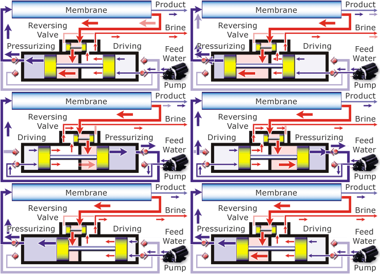
🔄 1. How Energy Recovery Changes the System
In a conventional watermaker, an electric motor drives a high-pressure plunger pump continuously. The pump supplies all the mechanical energy needed to raise the seawater to reverse osmosis pressure.
In a Clark Pump system, the electric feed pump operates at a much lower pressure. The Clark Pump then uses the pressure contained in the returning brine stream to intensify that feed pressure and produce the high pressure required by the membrane.
This architecture is particularly attractive for:
- Battery-powered sailing yachts.
- Solar-supported installations.
- Long-distance cruising boats.
- Systems designed to minimise generator or inverter use.
- Installations where low electrical consumption is more important than maximum production per hour.
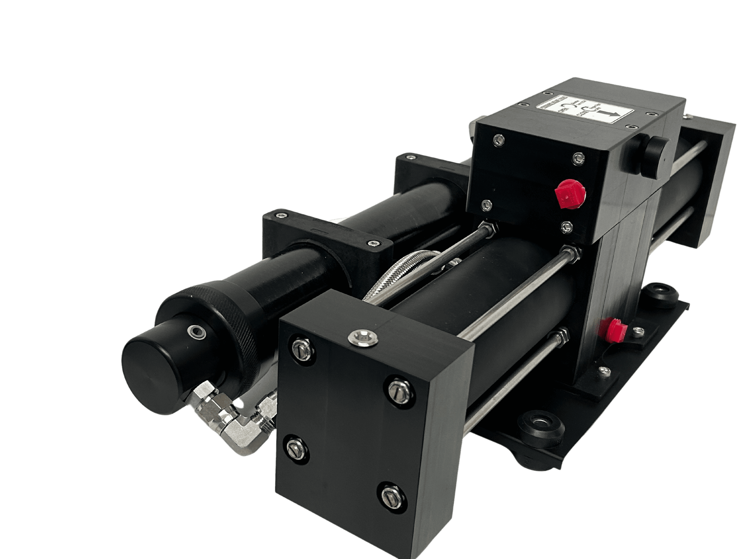
⚙️ 2. The Clark Pump as a Pressure Intensifier
A Clark Pump contains hydraulically linked pistons with different effective areas. Pressure acting on the larger side of the mechanism produces a higher pressure on the smaller high-pressure side.
The percentage assigned to a Clark Pump—commonly 10%, 15% or 20%—describes the relationship between the effective high-pressure piston area and the larger drive area.
In simplified terms, this percentage determines the approximate pressure multiplication ratio:
| Clark Pump rating | Approximate multiplication ratio | Example with 100 psi feed pressure |
|---|---|---|
| 10% | Approximately 10:1 | Approximately 1,000 psi output |
| 15% | Approximately 6.7:1 | Approximately 670 psi output |
| 20% | Approximately 5:1 | Approximately 500 psi output |
📐 3. Why a Lower Percentage Produces More Pressure
A lower percentage corresponds to a greater pressure multiplication ratio.
For example:
- A 20% unit multiplies pressure by approximately five.
- A 15% unit multiplies pressure by approximately 6.7.
- A 10% unit multiplies pressure by approximately ten.
- A theoretical 7% unit would multiply pressure by more than fourteen.
At first glance, a very low percentage may appear attractive because it can achieve high membrane pressure from relatively modest feed-pump pressure.
In practice, however, an excessively high multiplication ratio creates a narrow and potentially difficult operating window.
💥 4. Why BlueGold Avoids Clark Pumps Below 10%
A Clark Pump below 10% can generate very high membrane pressure from a feed pump that appears to be operating at a moderate pressure.
For example, if a feed pump pressure switch allows the system to approach approximately 120 psi, a very low-percentage Clark Pump may theoretically intensify that pressure beyond the safe working range of:
- RO membranes.
- Pressure vessels.
- High-pressure hoses.
- Fittings and connectors.
- Pressure sensors and gauges.
- The Clark Pump itself.
Cold seawater, high salinity, fouling or excessive membrane resistance can increase high-side pressure even further.
The objective is not to obtain the highest possible multiplication ratio, but to maintain a safe and controllable pressure range under real cruising conditions.
🌡️ 5. Why Operating Conditions Affect Clark Pump Pressure
The final high pressure in an energy-recovery system is not established by a conventional manually adjusted needle valve in the same way as a traditional plunger-pump watermaker.
It develops from the interaction between:
- Feed-pump pressure and flow.
- Clark Pump multiplication ratio.
- Membrane resistance.
- Feed-water temperature.
- Feed-water salinity.
- Membrane area and condition.
- Brine and product-water flow.
Conditions That Tend to Increase Pressure
- Colder seawater.
- Higher salinity.
- Reduced membrane permeability.
- Membrane fouling or scaling.
- Excessive feed-pump pressure.
- Insufficient membrane area for the applied flow.
- Restrictions in the high-pressure or brine circuit.
🧬 6. BlueGold Enhanced Clark Pumps
BlueGold systems use third-generation Enhanced Clark Pumps manufactured by ElectroMaax in Canada.
These units are intended for continuous seawater reverse osmosis operation and are selected according to the pressure, flow and membrane requirements of the complete watermaker.
BlueGold configurations use 10%, 15% and 20% versions depending on:
- The feed-pump pressure available.
- The required seawater flow.
- The total membrane surface area.
- The intended freshwater production.
- The expected seawater temperature and salinity.
- The pressure limits of the complete high-pressure circuit.
🔟 7. Typical Use of a 10% Clark Pump
A 10% Clark Pump offers a high pressure-multiplication ratio and can reach normal seawater RO pressure with comparatively modest feed pressure.
It is commonly suited to compact energy-recovery systems using one or two membrane elements, depending on the specific membrane format and feed-pump characteristics.
Possible membrane formats include:
- 2521 membranes.
- 3021 membranes.
- 2540 membranes
1️⃣5️⃣ 8. Typical Use of a 15% Clark Pump
A 15% Clark Pump has a lower multiplication ratio than the 10% version and therefore requires greater feed pressure to reach the same membrane pressure.
It can be advantageous in higher-flow systems with more membrane area, where the lower multiplication ratio creates a broader and more controllable feed-pressure range.
2️⃣0️⃣ 9. Typical Use of a 20% Clark Pump
A 20% Clark Pump produces approximately five times the feed pressure in simplified theoretical terms.
It therefore requires a feed pump capable of supplying a higher pressure, but the reduced multiplication ratio can make the high-pressure side easier to control in systems with substantial membrane area and high feed flow.
⚖️ 10. Comparing 10%, 15% and 20% Versions
| Characteristic | 10% | 15% | 20% |
|---|---|---|---|
| Approximate pressure ratio | 10:1 | 6.7:1 | 5:1 |
| Feed pressure required | Lowest | Medium | Highest |
| Pressure sensitivity | Highest | Moderate | Lowest of the three |
| Typical membrane arrangement | Compact or lower-area systems | Medium membrane area | Larger membrane area and flow |
| Feed-pump requirement | Lower pressure | Medium pressure | Higher pressure |
| Control priority | Strict overpressure protection | Balanced pressure and flow | Adequate feed-pump pressure and flow |
🔋 11. Feed Pump Selection Is Critical
The feed pump in a Clark Pump watermaker performs a different role from the low-pressure booster pump used in a conventional high-pressure watermaker.
It must provide:
- The flow required by the Clark Pump and membranes.
- The pressure needed for the selected intensification ratio.
- Stable operation over the full watermaker duty cycle.
- Enough reserve capacity for cold or high-salinity seawater.
- Protection against excessive discharge pressure.
🛡️ 12. Feed-Pump Cutoff Protection
The feed pump should include a correctly selected pressure cutoff or another reliable means of preventing excessive pressure.
The cutoff value must be chosen in relation to the Clark Pump percentage.
A pressure limit that is safe for a 20% unit may be dangerously high when used with a 10% unit.
Pressure protection should consider:
- Maximum normal feed pressure.
- Feed-pump bypass setting.
- Pressure-switch cutoff tolerance.
- Clark Pump ratio.
- Maximum vessel and membrane pressure.
- Possible pressure increase in cold or saline water.
🔁 13. Why BlueGold Prefers Feed Pumps with Adjustable Bypass
BlueGold favours vane feed pumps equipped with an internal bypass where suitable for the system.
The bypass allows the operator or installer to fine-tune the delivered pressure and flow without switching an entire pump on or off.
With an adjustable bypass, pressure and flow can often be reduced by only the amount required—for example 10–15%—to compensate for:
- Colder seawater.
- Higher regional salinity.
- Seasonal changes.
- A different membrane configuration.
- Normal variation in system resistance.
🎚️ 14. Adjusting Pressure Without Sacrificing Excessive Flow
Reducing feed pressure too aggressively also reduces the flow available to the Clark Pump and membranes.
This can lower production and reduce the cross-flow needed to carry rejected salts away from the membrane surface.
The objective is therefore to:
- Maintain the highest safe feed flow.
- Keep intensified pressure below the system limit.
- Preserve adequate brine flow.
- Avoid unnecessary electrical consumption.
- Maintain stable cycling of the Clark Pump.
The system should operate with the greatest safe flow and membrane pressure that the installed components and current seawater conditions permit.
🔍 15. Pressure Is a Result, Not a Direct Setting
In a conventional system, the operator normally adjusts a needle valve until the desired membrane pressure is reached.
In a Clark Pump system, high pressure emerges from the combination of:
- Feed pressure.
- Intensification ratio.
- Membrane resistance.
- Feed and brine flow.
- Temperature and salinity.
This means that a gradual increase in high pressure may be an early sign of:
- Colder water.
- Higher salinity.
- Membrane fouling.
- Restriction in the brine circuit.
- Excessive feed-pump pressure.
📊 16. Parameters to Monitor
A properly commissioned energy-recovery system should be monitored using several measurements rather than one pressure value alone.
| Parameter | What it helps diagnose |
|---|---|
| Feed-pump pressure | Confirms the input available to the Clark Pump |
| Membrane pressure | Shows the resulting intensified pressure |
| Feed flow | Confirms adequate water supply |
| Brine flow | Helps assess recovery and cycling |
| Product-water flow | Shows useful freshwater production |
| Product-water TDS | Confirms membrane rejection and water quality |
| Seawater temperature | Explains seasonal pressure and production changes |
| Seawater salinity | Explains changes in osmotic resistance |
Its percentage rating, feed-pump pressure, membrane area and seawater conditions must all be considered together. Correctly matched, an energy-recovery watermaker can deliver reliable seawater RO pressure with a fraction of the electrical consumption of a conventional high-pressure pump system.
In a Clark Pump watermaker, the vane pump is normally the main feed pump: it draws seawater from the intake and supplies the flow and pressure required by the Clark Pump.
A separate low-pressure booster pump can be added before it, but in most installations it is not strictly necessary.
A correctly installed vane pump is self-priming and can normally draw seawater directly from the through-hull. A booster pump is therefore an optional installation aid rather than a basic requirement.
⚙️ 1. Why a Booster Pump Is Usually Not Required
Rotary vane pumps have good self-priming capability and can create enough suction to lift seawater from the intake, provided that:
- The suction line is correctly sized.
- The hose run is reasonably short.
- There are no air leaks in the intake circuit.
- The through-hull and strainer are unobstructed.
- The pump is in good mechanical condition.
For this reason, a vane feed pump can normally be connected directly to the seawater intake without an additional centrifugal or magnetic-drive booster pump.
🌊 2. Recommended Installation Without a Booster Pump
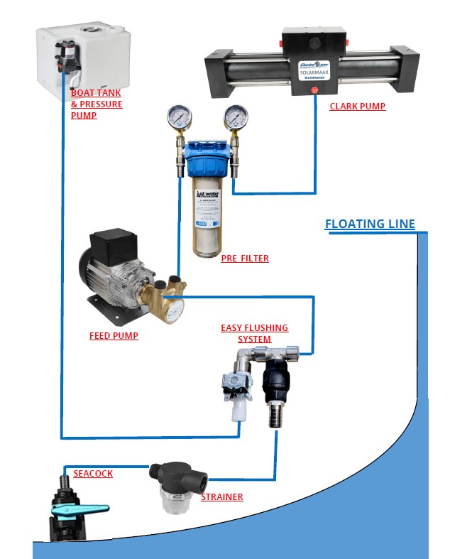
In the simplest arrangement, seawater follows this path:
This arrangement is compact, efficient and uses fewer electrical and hydraulic components.
For best results:
- Place the feed pump as low as practical.
- Keep the suction hose short and direct.
- Avoid unnecessary elbows and restrictions.
- Use a hose diameter appropriate for the required feed flow.
- Mount the pump where the intake and strainer can be inspected easily.
- Check all suction-side hose clamps and fittings for air leaks.
💨 3. Why Cavitation Must Be Avoided
Although vane pumps are self-priming, they should not be expected to operate continuously with a restricted or air-filled suction line.
If the pump cannot receive enough seawater, local pressure inside the pump can fall sufficiently for vapour bubbles to form. Their repeated formation and collapse is known as cavitation.
Cavitation may cause:
- Irregular or noisy pump operation.
- Reduced feed pressure and flow.
- Excessive vibration.
- Overheating.
- Damage to the internal vane surfaces.
- Chipping, cracking or complete failure of the vanes.
Vane pumps are relatively simple and economical components, but replacing one at sea is still unnecessary trouble. Regular intake inspection is far easier than repairing damage caused by cavitation.
🧽 4. Inspect the Seawater Strainer Regularly
The seawater strainer is the first defence against leaves, seaweed, shells, plastic fragments and other debris entering the feed circuit.
Because the vane pump is capable of producing significant suction, a partially blocked strainer may not immediately stop the system. Instead, the pump may continue operating with insufficient water supply.
Inspect the strainer:
- Before starting the watermaker after a long period of inactivity.
- More frequently in harbours, shallow bays and areas with seaweed.
- Whenever feed pressure or flow becomes unstable.
- Whenever the vane pump becomes noisier than usual.
- After operating in visibly polluted or debris-filled water.
⬆️ 5. What If the Feed Pump Is Above the Waterline?
A vane feed pump can still operate above the waterline because it is self-priming. A booster pump therefore remains optional even in this arrangement.
However, an above-waterline installation is less forgiving.
Greater attention must be paid to:
- The vertical lift from the through-hull to the pump.
- The total length of the suction hose.
- Air leaks at fittings and hose connections.
- Restrictions caused by the strainer or check valves.
- Maintaining the pump’s initial prime.
- Regular inspection of the entire intake path.
➕ 6. When a Booster Pump Can Be Useful
A booster pump may be worth adding when the installation has one or more difficult suction conditions.
Typical examples include:
- The vane pump must be installed well above the waterline.
- The seawater hose run is long.
- The intake circuit contains several bends or valves.
- The through-hull cannot be positioned close to the system.
- The boat’s layout makes reliable self-priming difficult.
- The system is intended to prime automatically after long idle periods.
- Additional protection against suction-side restrictions is desired.
In these cases, the booster pump does not replace the vane pump. It simply provides a small positive inlet pressure to the main feed pump.
🔄 7. Typical Arrangement with a Booster Pump
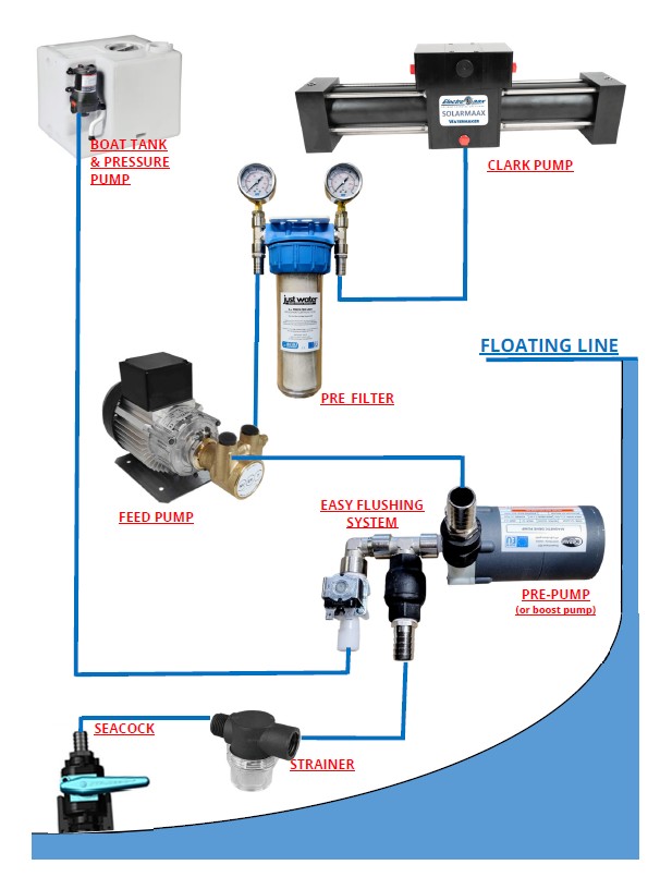
When a booster pump is installed, the seawater path becomes:
The booster pump should be:
- Suitable for continuous seawater use.
- Correctly sized for the full feed-flow requirement.
- Installed below the waterline whenever it is not self-priming.
- Protected from running dry.
- Wired to operate whenever the vane feed pump is running.
🛡️ 8. Why the Prefilter Is Installed After the Vane Feed Pump
The prefilter position in a Clark Pump system differs from the arrangement commonly used in a conventional high-pressure watermaker.
In the BlueGold energy-recovery layout, the fine prefilter is installed:
There are two important reasons for this arrangement.
Protecting the Clark Pump from External Contamination
The prefilter removes suspended particles from the seawater before they enter the Clark Pump and membrane circuit.
Protecting the Clark Pump from Vane Damage
If an internal vane were ever to chip or break, fragments would travel downstream from the feed pump.
Placing the prefilter after the feed pump allows the filter to capture these fragments before they can enter the Clark Pump.
📈 9. The Prefilter Must Be Rated for Feed-Pump Pressure
A vane feed pump does not operate at the very low pressure normally found upstream of a traditional watermaker’s high-pressure pump. Depending on the selected Clark Pump ratio and system configuration, the filter housing may be exposed to several bars of continuous pressure.
The prefilter housing must therefore be specifically rated for:
- The maximum normal feed-pump pressure.
- The feed-pump bypass setting.
- The pressure-switch cutoff value.
- Possible pressure surges during startup and cycling.
- Continuous marine operation.
🧰 10. Why BlueGold Uses a Cintropur Filter
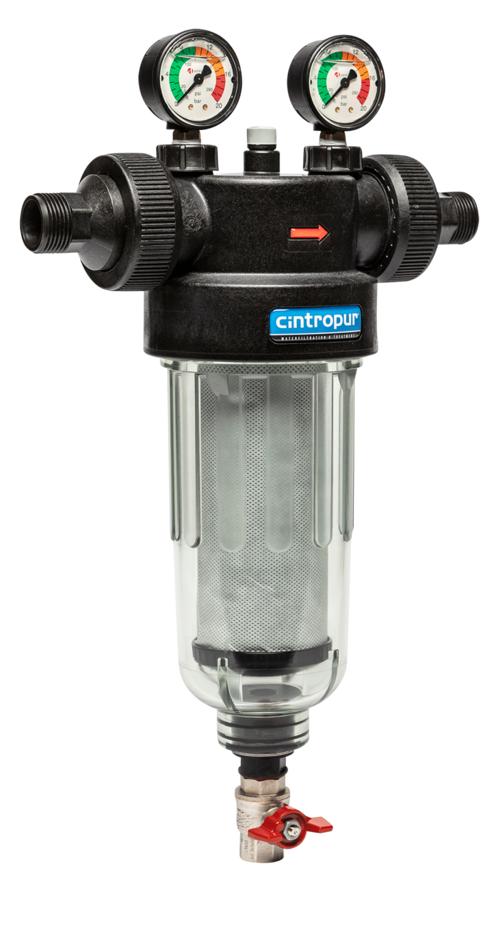
BlueGold supplies a Cintropur prefilter selected for operation at the pressures generated by the vane feed pump.
This type of housing is used because it provides:
- An appropriate pressure rating for the feed side of the Clark Pump.
- A robust housing and closure design.
- Good internal flow capacity.
- Low pressure loss when correctly sized.
- Easy inspection and maintenance.
- Reliable protection of the downstream Clark Pump.
🚫 11. Avoid Standard Domestic or Low-Cost Watermaker Housings
Below the result of a test using a standard bowl, which is perfectly suitable for systems with high pressure pump, but not with pressures over 7 bars generated by a vane pump
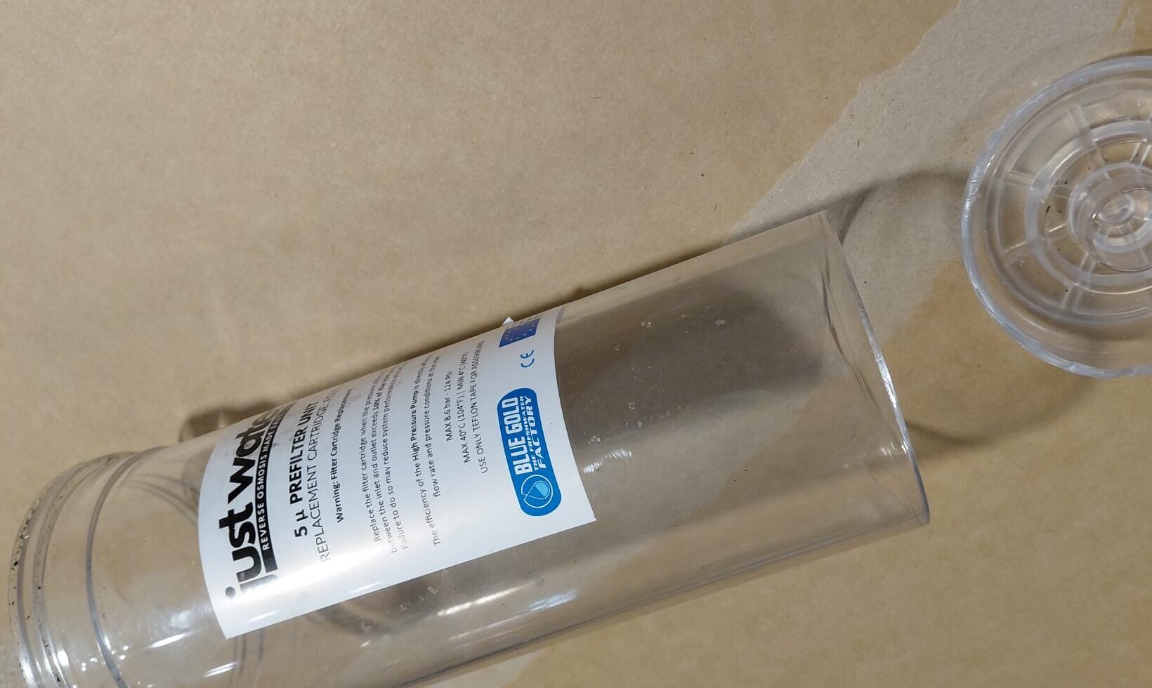
Many transparent filter housings used in conventional watermakers are installed on the low-pressure suction or booster side. They may be perfectly adequate in that position but unsuitable after a pressurised vane feed pump.
Lower-quality housings may be operating close to their structural limit at the pressures required by a Clark Pump system.
Possible failure modes include:
- Cracking of the transparent bowl.
- Deformation of the threaded closure.
- O-ring extrusion.
- Sudden leakage.
- Separation or rupture of the bowl under pressure.
Use only a housing specifically selected and rated for the maximum pressure of the energy-recovery system.
🔍 12. Monitor Pressure Before and After the Filter
Where practical, pressure measurement before and after the prefilter provides useful information about both feed-pump operation and filter condition.
An increasing pressure difference may indicate:
- A clogged filter element.
- Insufficient filter capacity.
- Excessive feed flow.
- A collapsed or incorrectly installed cartridge.
A clogged downstream filter can create several simultaneous problems:
- Higher pressure at the feed-pump outlet.
- Reduced flow to the Clark Pump.
- Unstable Clark Pump cycling.
- Reduced freshwater production.
- Increased risk of reaching the feed-pump cutoff pressure.
⚖️ 13. With or Without a Booster Pump?
| Installation condition | Booster pump recommendation |
|---|---|
| Vane pump below the waterline with a short intake hose | Normally unnecessary |
| Vane pump slightly above the waterline with a clean, airtight intake | Usually unnecessary, but regular inspection is important |
| Long suction hose or several restrictions | May be useful |
| Vane pump installed well above the waterline | Recommended for easier and more reliable priming |
| Automatic unattended priming required | Often advisable |
| Frequent blockage or cavitation symptoms | Correct the intake problem first; do not use a booster pump to hide a restriction |
✅ 14. Recommended Practice
- Install the vane feed pump below the waterline whenever possible.
- Use a dedicated, correctly sized seawater intake.
- Keep the suction circuit short, airtight and unrestricted.
- Inspect the seawater strainer regularly.
- Stop the system immediately if the vane pump cavitates.
- Add a booster pump only where the installation genuinely benefits from positive inlet pressure.
- Install the fine prefilter after the vane feed pump.
- Use a filter housing rated for the full feed-pump pressure.
- Do not use inexpensive domestic housings on the pressurised feed side.
- Mount every filter housing where leakage can be detected and contained.
A vane feed pump can normally prime and feed the Clark Pump on its own, especially when mounted below the waterline. The essential requirements are an unobstructed intake, a clean strainer, protection from cavitation and a pressure-rated prefilter positioned downstream of the vane pump.
The required space depends on whether the system is modular or frame-mounted. A modular installation allows pumps, filters, vessels and controls to be distributed around available machinery spaces, but all serviceable components must remain accessible.
A conventional system is mechanically straightforward and usually easier to understand, maintain and source parts for. Energy recovery systems reduce electrical consumption but use more specialised hydraulic components and may require a more specific installation and maintenance approach.
The Freshwater Cycle After the Membranes
Once freshwater has passed through the reverse osmosis membranes, it must still be measured, checked and directed to the correct destination. In this section, we’ll follow the product-water flow through the flow meter, TDS monitoring system and diverting valve, from the membrane outlet to either the freshwater tank or the temporary discard line.
After leaving the reverse osmosis membranes, the product water may look perfectly clear even when its salt content is still too high. For this reason, water quality should be checked before the freshwater is allowed to enter the boat’s tank.
In BlueGold systems, TDS is measured immediately downstream of the membrane outlet. The sensor continuously monitors the product water and sends an electrical signal to the touch-screen controller, where the value is processed, displayed and used to control the freshwater diverting sequence.
Dissolved salts are invisible, so product-water quality cannot be judged by appearance alone.
💧 1. What Does TDS Mean?
TDS stands for Total Dissolved Solids. It is commonly expressed in:
- ppm — parts per million
- mg/L — milligrams per litre
For the low concentrations normally found in freshwater, these two units are often treated as approximately equivalent.
A TDS reading gives an estimate of the total amount of dissolved ionic material in the water, including salts and minerals.
⚡ 2. Why Conductivity Can Be Used to Estimate TDS
Pure water conducts very little electricity. When salts dissolve in water, they separate into electrically charged ions, which increase conductivity.
A TDS sensor measures this conductivity and converts it into a value that is easier for the operator to interpret.
In practical terms:
- Higher conductivity usually means more dissolved salts.
- Lower conductivity usually means less dissolved salt.
- A healthy seawater RO membrane should reduce conductivity dramatically.
📍 3. Where TDS Is Measured in a BlueGold System
The TDS sensor is installed immediately after the product-water outlet from the membrane or membrane group.
The typical sequence is:
The exact order of the TDS sensor and flow meter may vary according to the hydraulic layout, but both are installed before the water is finally accepted into the tank.
Positioning the sensor close to the membrane outlet allows the controller to evaluate the actual product water before it becomes mixed with water already present in the tank.
🖥️ 4. TDS Monitoring in BlueGold Systems
BlueGold systems use a compact electronic TDS interface based on a widely available microcontroller-compatible measurement principle, commonly used in Arduino projects.
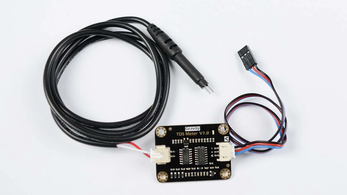
The system consists of:
- A conductivity or TDS probe in contact with the product water.
- An electronic interface that converts the probe signal into a stable electrical measurement.
- A connection to the BlueGold touch-screen controller.
- Software that processes, compensates and displays the reading.
The controller receives the sensor signal, converts it into a TDS value and displays the result directly on the touch screen.
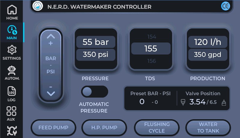
Blue Gold non proprietary OPEN SOURCE control panel for watermakers based on ESP32-P4 available on Github for non commercial purposes.
- The product-water quality is visible throughout the operating cycle.
- The controller can detect when the initial high-TDS water has cleared.
- The diverting valve can be operated automatically.
- Unexpected changes in membrane performance can be detected quickly.
- The operator does not need to collect repeated manual samples.
🚿 6. Why TDS Is Normally High at Startup
When a watermaker has been stopped, water remains inside the membrane and product-water lines.
During this period:
- Salt can diffuse across the membrane.
- Residual water may become more concentrated.
- Freshwater used for flushing may mix with the first new product water.
- Preservation or cleaning residues may still be present after maintenance.
As a result, the first product water may not represent normal membrane performance.
The system should therefore discharge this initial water overboard until:
- The TDS value has stabilised.
- The reading is below the chosen acceptance threshold.
- Any cleaning or preservation residue has been fully removed.
🎚️ 7. TDS and the Diverting Valve
In an automated system, the controller compares the measured TDS with a programmed limit.
If the reading is too high:
- The diverting valve sends the product water to discard.
- The freshwater tank remains isolated.
Once the TDS falls below the selected value and remains stable for the required time:
- The controller changes the diverting valve position.
- Accepted product water is sent to the freshwater tank.
🌡️ 8. Temperature Affects TDS Measurement
Electrical conductivity changes with water temperature. The same water sample can therefore produce different conductivity readings at different temperatures.
Many electronic TDS systems use temperature compensation to convert the measurement to a standard reference temperature, commonly 25°C.
Where no automatic compensation is available, readings should be compared under similar temperature conditions.
🧮 9. TDS Conversion Factors
Conductivity and TDS are related, but they are not identical measurements.
Electronic meters normally estimate TDS using a conversion factor:
Different instruments may use different factors, depending on the salts they are intended to approximate.
This means that two correctly functioning meters can show slightly different TDS values when testing the same sample.
🧪 10. Manual TDS Testing
A fully automatic TDS system is convenient, but manual testing remains a valid alternative.
The simplest procedure is:
- Allow the watermaker to start producing water.
- Keep the product water directed to discard.
- Collect a fresh sample in a clean glass or container.
- Insert a portable TDS meter into the sample.
- Wait for the reading to stabilise.
- Rinse the meter after use with clean freshwater.
- Direct water to the tank only after an acceptable reading has been confirmed.
📱 11. Portable TDS Meters
Many portable TDS instruments are available, ranging from simple pocket meters to professional conductivity instruments.
Basic Pocket Meters
- Compact and inexpensive.
- Useful for occasional checks.
- Easy to keep as an emergency backup.
- Accuracy and repeatability vary significantly.
- Some models cannot be recalibrated.
Better-Quality Portable Instruments
- More stable readings.
- Replaceable or higher-quality probes.
- Calibration functions.
- Automatic temperature compensation.
- Clearer documentation of measurement range and accuracy.
A very inexpensive meter may still be useful as a rough indicator, but it should not automatically be trusted as a precision reference.
🔍 12. What to Check When Buying a Portable Meter
- Measurement range appropriate for low-TDS product water.
- Published accuracy specification.
- Resolution at low conductivity.
- Automatic temperature compensation.
- Possibility of calibration.
- Availability of calibration solution.
- Replaceable battery.
- Water-resistant construction.
- Stable readings rather than rapidly changing numbers.
🧭 13. Use a Portable Meter as a Reference
Even when continuous electronic monitoring is installed, keeping a separate handheld meter onboard is good practice.
It can be used to:
- Verify the installed sensor.
- Check calibration.
- Test water directly at the membrane outlet.
- Compare tank water with newly produced water.
- Continue operating manually if the fixed sensor fails.
🛠️ 14. Calibration
All conductivity-based TDS sensors should be checked periodically.
Calibration should be carried out using a proper conductivity or TDS reference solution with a known value.
A good calibration procedure includes:
- Rinse the probe with clean water.
- Shake off excess water without wiping the sensing surfaces aggressively.
- Place the probe in fresh calibration solution.
- Allow the reading and temperature to stabilise.
- Adjust the meter or controller to the reference value.
- Rinse the probe after calibration.
🧼 15. Sensor Maintenance
The TDS probe is installed on the freshwater side, so it is generally exposed to a much cleaner environment than seawater sensors. Even so, contamination can affect readings.
Possible causes include:
- Mineral deposits.
- Biofilm inside stagnant product-water tubing.
- Residue from membrane cleaning chemicals.
- Oil or grease contamination.
- Air bubbles trapped around the probe.
Inspect and clean the sensor according to its design and manufacturer instructions.
💨 16. Avoid Air Around the Sensor
The probe must remain properly wetted by product water. Air bubbles around its sensing surfaces can produce unstable or falsely low readings.
For reliable installation:
- Position the sensor where the chamber fills completely.
- Avoid a high point where air can collect.
- Maintain a steady product-water flow.
- Purge the line after maintenance.
- Observe whether readings become stable once air has cleared.
📊 17. What Is an Acceptable TDS Value?
There is no single universal number that applies to every installation, tank and operating condition.
The selected acceptance limit should consider:
- The quality of the feed seawater.
- The membrane manufacturer’s rejection specification.
- Feed-water temperature.
- Operating pressure.
- The intended use of the product water.
- Local drinking-water requirements.
- The accuracy of the installed measuring device.
📈 18. Causes of Increasing Product-Water TDS
A higher reading does not always mean that the membrane must be replaced.
Possible causes include:
- Higher seawater temperature.
- Higher feed-water salinity.
- Insufficient membrane pressure.
- Startup salt passage.
- Incorrect sensor calibration.
- Air bubbles around the probe.
- Contaminated sampling equipment.
- Damaged membrane O-rings or permeate seals.
- Excessive product-water backpressure.
- Membrane fouling, ageing or chemical damage.
🚨 19. Typical Warning Signs
| Observed behaviour | Possible explanation |
|---|---|
| High TDS only during startup | Normal initial salt passage; continue diverting to discard |
| TDS gradually falls and stabilises | Normal startup behaviour |
| TDS remains persistently high | Low pressure, high salinity, membrane or sealing problem |
| Reading changes rapidly or erratically | Air bubbles, poor electrical connection or sensor contamination |
| Fixed sensor and handheld meter disagree | Calibration, temperature compensation or conversion-factor difference |
| TDS rises suddenly during normal operation | Pressure loss, seal failure, flow change or sensor fault |
✅ 20. Recommended BlueGold Practice
- Measure product-water TDS immediately after the membranes.
- Keep the water directed to discard during startup.
- Transfer water to the tank only after the TDS has stabilised below the selected limit.
- Use continuous monitoring where automatic control is desired.
- Keep a portable meter onboard as an independent reference.
- Calibrate both fixed and portable instruments periodically.
- Do not rely blindly on extremely inexpensive no-brand meters.
- Investigate trends before replacing membranes.
- Keep the sensor chamber free from air and contamination.
- Record normal operating values for future comparison.
BlueGold systems measure product-water conductivity continuously, process the signal through the touch-screen controller and use the result to display water quality and control the diverting valve. Manual sampling with a reliable portable meter remains a valid alternative—and an excellent backup—but the instrument must be suitable, calibrated and treated as a measuring device rather than a decorative number generator.
Measuring product-water flow is useful for confirming actual watermaker output, comparing performance over time and detecting changes caused by temperature, salinity, pressure or membrane condition.
BlueGold systems use two different Hall-effect flow sensors, selected according to the expected freshwater production range. Each sensor generates electrical pulses as water passes through it, allowing the touch-screen controller to calculate and display the current flow rate and total water produced.
⚡ 1. Hall-Effect Flow Sensors
A Hall-effect flow sensor contains a small internal rotor. As product water passes through the sensor, the rotor turns and produces a series of electrical pulses.
The controller counts these pulses and converts them into:
- Instantaneous product-water flow.
- Litres produced during the current cycle.
- Total accumulated production, where configured.
Because very small and larger watermakers operate at quite different flow rates, BlueGold uses two sensor sizes rather than forcing one sensor to cover every application.
📊 2. Variable-Area Flow Meters
A variable-area flow meter, often called a rotameter, provides a simple mechanical indication of product-water flow.
Water enters the lower part of the transparent tapered tube and lifts a float. The height of the float corresponds directly to the flow rate shown on the graduated scale.
Main advantages include:
- No electrical supply.
- No electronic calibration.
- Immediate visual reading.
- Very low cost.
- Easy troubleshooting.
- Good reliability in simple manual systems.
🔄 3. Clark Pump Systems and Pulsating Flow
Small Clark Pump watermakers do not always produce a perfectly continuous product-water stream. The reciprocating action of the energy-recovery unit can create visible flow pulsations.
An electronic Hall sensor will still detect this flow, but the displayed instantaneous value may fluctuate unless the controller applies suitable averaging.
A variable-area flow meter naturally dampens these pulsations and gives the operator a clear visual indication of the average production rate.
⚖️ 4. Why BlueGold Often Prefers Mechanical Flow Measurement on Small ERP Systems
In compact energy-recovery watermakers, the Clark Pump automatically establishes membrane pressure according to feed pressure, membrane resistance, temperature and salinity.
The operator therefore does not need a complex electronic flow-control system simply to make the watermaker function correctly.
For these smaller systems, BlueGold often prefers a variable-area flow meter because it:
- Handles pulsating product-water flow well.
- Provides all the information needed during normal operation.
- Avoids unnecessary sensors, wiring and software.
- Reduces the number of possible failure points.
- Keeps the system easier to understand and maintain.
- Avoids increasing the final system price without a meaningful practical benefit.
Where automatic monitoring adds real value, BlueGold uses correctly sized Hall-effect sensors. In small Clark Pump systems, however, a reliable mechanical flow meter often provides a clearer, simpler and more economical solution.
🧭 5. Which Type Should You Choose?
| Application | Recommended solution |
|---|---|
| Automatic system with touch-screen monitoring | Hall-effect flow sensor matched to the production range |
| Higher product-water flow | Larger Hall-effect sensor with suitable internal bore |
| Low-output conventional watermaker | Small Hall sensor or variable-area flow meter |
| Small Clark Pump watermaker | Variable-area flow meter usually preferred |
| Simple fully manual installation | Variable-area flow meter |
Electronic Hall sensors are ideal where production data must be displayed or recorded by the controller, while variable-area meters remain an excellent choice for compact Clark Pump systems with low and naturally pulsating product-water flow.
The diverting valve is installed downstream of the membranes and water-quality monitoring system. Its purpose is simple: it directs product water either to the freshwater tank or to the discard line.
During startup, product-water TDS is normally higher and may take some time to stabilise. Until the measured value falls below the selected limit, the water is sent to discard. Once the water quality is acceptable, the valve redirects the flow toward the freshwater tank.
⚡ 1. The BlueGold Electric Diverting Valve
BlueGold systems use an electrically operated three-way solenoid valve controlled directly by the touch-screen display.
The controller evaluates the TDS reading and selects the correct outlet:
- High or unstable TDS: Product water is sent to discard.
- Acceptable and stable TDS: Product water is sent to the freshwater tank.
The valve can also be operated according to the programmed startup and shutdown sequence of the watermaker.
Membranes → TDS monitoring → flow monitoring → diverting valve → tank or discard
🧲 2. Solenoid Valve Versus Motorised Valve
A solenoid valve is different from a motorised ball valve.
The BlueGold diverting valve uses an electromagnetic solenoid to change the internal flow path almost immediately when electrical power is applied or removed.
A motorised valve instead uses a small electric motor and gearbox to rotate a ball or other valve element between positions. It normally moves more slowly and contains additional mechanical parts.
🕹️ 3. Manual Alternative for DIY Systems
In a manually operated DIY watermaker, the electric solenoid valve can be replaced by a standard three-way ball valve suitable for potable water.
The operator simply selects between:
- The discard outlet during startup and whenever water quality is uncertain.
- The freshwater tank once an acceptable TDS reading has been confirmed.
✅ 4. Recommended Practice
- Default the system to discard during startup.
- Send water to the tank only after TDS has stabilised below the selected limit.
- Use materials suitable for potable water.
- Select a valve with minimal flow restriction.
- Clearly label the tank and discard positions on manual valves.
- Return the valve to discard before the next startup.
The BlueGold touch-screen controller operates an electric three-way solenoid valve automatically, while a manual three-way ball valve provides an equally valid solution for a simple self-built watermaker.
A correctly operating reverse osmosis membrane provides an extremely effective microbiological barrier. Product water leaving an intact membrane therefore has a very low microbiological load, and an ultraviolet lamp is normally unnecessary between the watermaker and the freshwater tank.
🚫 1. Why UV Before the Tank Has Little Value
Installing a UV lamp directly after the watermaker treats water that has already passed through the reverse osmosis membrane.
Once this water enters the freshwater tank, however, it may be exposed again to:
- Microorganisms already present inside the tank.
- Biofilm in hoses and fittings.
- Air entering through the tank vent.
- Water loaded from a marina or shore supply.
- Contamination introduced during maintenance or filling.
✅ 2. The Correct Position for a UV Lamp
If UV disinfection is desired, it should be installed downstream of the freshwater tank, on the water-supply side of the system.
For maximum protection, the lamp should be located as close as practical to the point of use, such as the drinking-water tap.
Freshwater tank → pressure pump and filters → UV lamp → drinking-water tap
Positioning the lamp close to the outlet also reduces the length of pipe in which bacteria could grow after treatment.
📍 3. Simple Placement Summary
| UV lamp position | Recommendation |
|---|---|
| Between the watermaker and tank | Normally unnecessary |
| Immediately after the tank, before long distribution pipes | Provides treatment, but allows possible recontamination downstream |
| Close to the drinking-water tap | Preferred position when UV treatment is required |
Its most useful position is after the storage tank and as close as practical to the final drinking-water outlet, where it can treat any contamination introduced during storage or distribution.
Reverse osmosis removes not only salts and contaminants, but also most of the natural minerals and alkalinity present in seawater. The resulting product water is very soft and poorly buffered, which means that its pH can change easily and the water may become chemically aggressive toward tanks, fittings and distribution components.
💧 1. Why RO Water May Need Stabilisation
Freshly produced reverse osmosis water contains very little calcium, magnesium and bicarbonate alkalinity. Even when its measured pH appears acceptable, its low buffering capacity means that it can absorb carbon dioxide and become mildly acidic.
Over time, unstabilised RO water may contribute to:
- Corrosion of metallic tanks, fittings and plumbing components.
- Leaching of metals from unsuitable distribution materials.
- An unstable or slightly acidic taste.
- Large pH variations caused by even small chemical changes.
Low alkalinity means that the water has very little ability to resist changes in pH. Stabilisation therefore aims to improve both mineral content and buffering capacity.
🪨 2. The BlueGold Dolomite Postfilter
BlueGold uses a simple postfilter containing only calcined dolomite.
As the product water passes through the filter medium, it dissolves a small and controlled quantity of calcium and magnesium compounds. This helps:
- Increase mineral content.
- Raise and stabilise pH.
- Increase alkalinity and buffering capacity.
- Reduce the aggressive character of very low-mineral RO water.
- Improve the taste of the final drinking water.
📍 3. Where the Postfilter Is Installed
The remineralisation filter is installed on the product-water line after the membranes and water-quality control components, before the water enters the freshwater tank.
Membranes → TDS monitoring → flow monitoring → diverting valve → dolomite postfilter → freshwater tank
Only water accepted for storage should pass through the remineralisation filter. Startup water being sent to discard does not need to be treated.
⚖️ 4. When Remineralisation Is Most Important
We particularly recommend a dolomite postfilter when the boat’s freshwater tanks are filled almost exclusively with water produced by the watermaker.
In this situation, the stored water receives very little natural mineral content from other sources, so its alkalinity may remain extremely low.
If the tank is also filled periodically with marina or municipal water, the minerals and alkalinity already present in that water may partially stabilise the mixed tank contents. Remineralisation can still be beneficial, but it becomes less critical.
Watermaker water only → postfilter strongly recommended.
Regular mixture with shore water → postfilter optional, depending on the quality and materials of the onboard system.
🔍 5. Simple Maintenance
Calcined dolomite is gradually consumed as water passes through the filter. The medium should therefore be inspected and replenished or replaced periodically.
The service interval depends on:
- The quantity of water produced.
- The initial pH and alkalinity of the RO water.
- The size of the filter housing.
- The contact time between the water and the medium.
After replacing or refilling the medium, flush the postfilter until the water runs clear before directing it to the tank.
A simple calcined-dolomite postfilter adds calcium and magnesium, stabilises the pH and reduces the corrosive character of the water. It is especially recommended when the freshwater tanks are supplied only—or almost only—by the watermaker.
High Pressure Side
The high-pressure side of a marine watermaker begins after the high-pressure pump and continues through the membrane vessels, pressure-control components and brine discharge line. This part of the system operates at seawater reverse-osmosis pressure and must be assembled only with correctly rated hoses, fittings, valves, gauges and safety devices.
In this section, we focus on the components that contain, control and safely discharge high-pressure seawater. Correct installation is essential: a small fitting, washer, hose bend or thread-sealing mistake can create leaks, pressure instability or unsafe operating conditions.
High-pressure hoses and fittings connect the pump, membrane vessels, pressure-regulating valve, pressure gauge and brine discharge circuit. They may look like simple accessories, but they are safety-critical components of every conventional marine watermaker.
The high-pressure circuit normally operates at approximately 55–60 bar in seawater reverse osmosis systems. Every hose, fitting, nipple, washer, valve and gauge connected to this circuit must therefore be selected, assembled and inspected as part of one pressure-rated system.
Thread type, sealing method, pressure rating, material compatibility and mechanical support all matter.
🔩 1. What the High-Pressure Connections Do
The high-pressure connections carry seawater from the high-pressure pump to the membrane vessels and then from the membrane brine outlet to the regulating valve and discharge line.
They must:
- Contain the full operating pressure of the system.
- Withstand pressure pulses from the high-pressure pump.
- Remain leak-free during repeated start and stop cycles.
- Resist seawater corrosion.
- Allow safe routing between components installed in different parts of the boat.
- Maintain the correct flow path through the membrane vessels.
Short, supported, correctly routed hoses with clean fittings are normally better than complicated hose runs with many adapters.
📏 2. Use Only Pressure-Rated Components
All components on the high-pressure side must be rated above the maximum pressure that the system can reach, not merely above the normal operating pressure.
This includes:
- High-pressure hoses.
- Crimped or reusable hose fittings.
- Nipples and adapters.
- Membrane-vessel fittings.
- Pressure gauges.
- Pressure-regulating valves.
- Relief valves and safety devices.
- Threaded plugs and unused ports.
A high-quality pump and vessel do not make an underrated hose, gauge or adapter safe.
🧵 3. Thread Types Must Not Be Confused
Marine watermaker components may use different thread standards, and they do not all seal in the same way. Some threads seal on the thread itself, while others use a cone, washer, O-ring or flat sealing surface.
Common examples include:
- NPT tapered threads: Normally seal on the tapered thread with a suitable sealant or PTFE tape where specified.
- BSPP parallel threads: Do not seal by taper alone; they normally require a washer, O-ring, cone or dedicated sealing face.
- 60° cone fittings: Seal on the metal cone surface, not on the thread.
- O-ring fittings: Seal with the O-ring and must not be treated like tapered pipe threads.
Before applying PTFE tape or liquid sealant, identify how that specific fitting is designed to seal.
🧴 4. PTFE Tape, Liquid Sealant and Washer-Sealed Connections
Using the wrong sealing method is one of the most common causes of problems in high-pressure plumbing.
Where PTFE Tape May Be Used
PTFE tape may be used on suitable tapered threads, such as selected NPT connections, when specified by the component instructions.
- Apply only a small number of neat turns.
- Wrap in the tightening direction.
- Keep the first thread reasonably clear.
- Do not allow loose tape to enter the hydraulic circuit.
- Do not use excessive tape to compensate for damaged or incompatible threads.
Where PTFE Tape Should Not Be Used
Do not apply PTFE tape to fittings that seal with:
- A copper, aluminium or bonded washer.
- An O-ring.
- A flat gasket.
- A 60° cone.
- A compression surface.
- A manufacturer-supplied sealing washer.
If a high-pressure nipple seals with a supplied washer, the washer creates the seal. Adding PTFE tape to the thread can prevent correct seating and may introduce loose material into the high-pressure circuit.
🔧 5. Do Not Over-Tighten Fittings
High-pressure fittings must be tight enough to seal, but excessive force can damage threads, distort sealing faces, crack plastic or Delrin components, flatten washers incorrectly or make future maintenance difficult.
Over-tightening can cause:
- Damaged female threads in pump heads or vessel end caps.
- Distorted cone or washer sealing surfaces.
- Cracked polymer components.
- Leaks that become worse after pressure cycling.
- Difficulty removing fittings without damaging the component.
If a fitting does not seal with the correct sealing method and reasonable tightening force, stop and check the thread type, washer, O-ring and fitting compatibility.
🌀 6. Hose Routing and Bend Radius
High-pressure hoses must be routed so that they are not twisted, kinked, stretched or forced into sharp bends.
Good routing practice includes:
- Respecting the minimum bend radius of the hose.
- Avoiding tight bends immediately after a fitting.
- Preventing torsion during installation.
- Keeping hoses clear of belts, pulleys, couplings and hot surfaces.
- Avoiding chafe against bulkheads, lockers or metal edges.
- Supporting long hose runs with suitable clamps.
- Leaving enough movement allowance for vibration and service access.
Poor routing, twisting and chafe are just as important as pressure rating.
⚙️ 7. Pressure Pulses and Vibration
Positive-displacement high-pressure pumps create pulsating flow. The hoses and fittings must tolerate these pressure pulses and the vibration generated by the pump and motor assembly.
To reduce mechanical stress:
- Mount the pump and motor assembly securely.
- Use suitable vibration-damping mounts where appropriate.
- Avoid using rigid pipe where flexible high-pressure hose is required.
- Support hoses without clamping them so tightly that they are damaged.
- Check fittings again after the first operating hours.
A connection that remains dry during a short test may reveal a small leak only after pressure cycling and vibration.
🌊 8. Material Compatibility
High-pressure fittings are exposed to seawater and must be made from suitable materials for marine reverse-osmosis service.
Suitable materials may include:
- AISI 316L stainless steel where specified.
- Suitable high-pressure brass or nickel-plated brass components where appropriate.
- Manufacturer-approved polymer or Delrin components in vessel end caps.
- Correct sealing washers and O-rings compatible with seawater and operating pressure.
A fitting may look correct but still be unsuitable for seawater, pressure cycling or the specific sealing geometry required.
🚫 9. Common Mistakes
- Using low-pressure plumbing fittings on the high-pressure side.
- Mixing NPT and BSP threads incorrectly.
- Adding PTFE tape to cone, washer or O-ring sealed fittings.
- Over-tightening fittings into Delrin or polymer parts.
- Routing hoses with sharp bends or torsion.
- Leaving hoses unsupported where vibration is present.
- Allowing hoses to rub against edges or moving parts.
- Using too many adapters instead of the correct fitting.
- Ignoring small salt deposits around fittings after operation.
🔍 10. Leak Inspection
High-pressure leaks are not always obvious at first. A very small leak may evaporate quickly and leave only a salt trace after the system stops.
During inspection, look for:
- Dampness around threaded fittings.
- Salt crystals or white deposits.
- Corrosion marks around metal fittings.
- Water spray or mist under pressure.
- Hose cover damage or swelling.
- Movement of fittings during startup or shutdown.
Stop the system, release pressure and inspect safely.
✅ 11. High-Pressure Hose and Fitting Checklist
| Check | Recommended condition |
|---|---|
| Pressure rating | All components rated above the maximum possible system pressure |
| Thread type | Correctly identified before assembly |
| Sealing method | Matched to the fitting: thread, washer, cone or O-ring |
| PTFE tape | Used only where specified; never on washer, cone or O-ring seals |
| Hose routing | No sharp bends, twisting, chafe or unsupported long runs |
| Vibration | Hoses supported and protected from pump movement |
| Materials | Suitable for seawater and high-pressure RO service |
| Inspection | Checked during commissioning and after first operating hours |
Correct hoses, compatible fittings, proper sealing methods and good routing make the difference between a clean, reliable installation and a system that leaks, vibrates or becomes unsafe under pressure.
Pressure regulation is one of the most important operations in a conventional marine watermaker. After the high-pressure pump has started and stable feed-water flow has been established, the operator or control system must create the correct backpressure on the brine outlet so that the reverse osmosis membrane can produce freshwater efficiently and safely.
In a traditional manual system, this is done with a high-pressure needle valve. In an automated BlueGold system, N.E.R.D. 2 can control pressure automatically using a dedicated regulating valve driven by a stepper motor.
pressure is created by restricting the brine flow leaving the membrane vessel. The difference is whether the adjustment is made by hand or by an automatic controller.
🎛️ 1. What the Pressure-Regulating Valve Does
The pressure-regulating valve is installed on the concentrate, or brine, outlet of the membrane circuit. By partially restricting the outgoing brine flow, it creates the backpressure required for seawater reverse osmosis.
Without enough backpressure, the system will not develop the pressure required for useful freshwater production. With too much backpressure, the pump, membrane, pressure vessel, hoses and fittings may be exposed to unsafe loads.
- Too little pressure: low freshwater production and poor system efficiency.
- Correct pressure: stable membrane operation and predictable production.
- Too much pressure: excessive motor load, possible overpressure and risk of component damage.
The high-pressure pump provides flow. The regulating valve creates pressure by restricting that flow on the brine side.
🪡 2. Manual Needle Valve Operation
A needle valve allows fine manual adjustment of the brine restriction. During startup, the valve should normally be open. Once the feed pump and high-pressure pump are running correctly and seawater flow is stable, the valve is closed gradually until the desired operating pressure is reached.
The adjustment should always be smooth and progressive.
- Start with the pressure-regulating valve open.
- Establish stable feed-water flow.
- Start the high-pressure pump.
- Confirm that brine is flowing freely to discharge.
- Close the needle valve slowly while watching the high-pressure gauge.
- Stop increasing pressure when the target operating pressure is reached.
- Verify product-water flow and TDS after the system has stabilised.
A sudden restriction can make pressure rise very quickly and may stress the pump, membrane, vessel and fittings.
📏 3. Where the Gauge or Pressure Sensor Belongs
The high-pressure gauge or pressure sensor should measure the pressure before the pressure-regulating valve, not after it.
This allows the operator or controller to read the actual pressure inside the membrane circuit. A gauge installed after the regulating valve would read the discharge side and would not correctly represent membrane operating pressure.
High-pressure pump → membrane vessel → pressure gauge or pressure sensor → pressure-regulating valve → brine discharge.
Depending on the system layout, the sensor or gauge may be installed near the membrane outlet, on the high-pressure manifold or close to the regulating valve, but it must read the pressure upstream of the final restriction.
🤖 4. Automatic Pressure Control with N.E.R.D. 2
N.E.R.D. 2 – Advanced Watermaker Controller can automate the pressure-regulation process. Instead of requiring the operator to manually turn a needle valve, the controller reads the system pressure through a pressure sensor and adjusts a special high-pressure regulating valve using a stepper motor.
This allows the system to raise, stabilise and reduce pressure in a controlled and repeatable way.
It automates the same operation normally performed by hand: increasing or decreasing the brine-side restriction until the desired pressure is reached.
How the Automatic System Works
- The pressure sensor continuously measures high-pressure circuit pressure.
- The controller compares the measured value with the target pressure.
- The stepper motor turns the regulating valve in small controlled increments.
- If pressure is too low, the valve is closed slightly.
- If pressure is too high, the valve is opened slightly.
- The system can react to changing temperature, salinity, filter condition and membrane behaviour.
It allows small, repeatable movements. This is much more suitable for pressure control than a simple on/off valve.
⚖️ 5. Manual vs. Automatic Pressure Regulation
| Feature | Manual needle valve | N.E.R.D. 2 automatic control |
|---|---|---|
| Adjustment method | Operator turns the valve manually | Stepper motor adjusts the regulating valve |
| Pressure feedback | Operator reads the pressure gauge | Controller reads the pressure sensor |
| Startup | Requires manual gradual pressure increase | Can perform controlled pressure ramping |
| Stability | Depends on operator attention | Can continuously correct pressure variations |
| Complexity | Very simple and easy to understand | Requires sensor, controller, motor and suitable valve |
| Best suited for | Simple manual DIY systems | Automatic and semi-automatic watermakers |
🧭 6. Which Solution Should You Choose?
A manual needle valve is still an excellent solution for simple, robust and easily serviceable watermakers. It is inexpensive, intuitive and requires no electronics.
Automatic pressure control is preferable when the system is designed for push-button operation, remote monitoring, repeatable startup sequences or integration with a more complete watermaker controller.
- Choose a manual needle valve when simplicity, low cost and direct operator control are priorities.
- Choose N.E.R.D. 2 automatic pressure control when repeatability, automation and system protection are more important.
Whether controlled by hand or by N.E.R.D. 2, the brine-side restriction must be adjusted carefully so that the membrane operates at the correct pressure without exceeding the safe limits of the system.
The high-pressure gauge, pressure sensor and overpressure protection devices allow the watermaker to be operated safely. They show what is happening inside the membrane circuit and prevent accidental overpressure if the regulating valve is closed too far, blocked or incorrectly controlled.
A conventional watermaker should never rely only on the operator’s memory or on the assumed position of a valve. Pressure must be measured, displayed and limited by suitable safety devices.
It depends on correct measurement, correct valve position, correctly rated components and a reliable method of stopping or relieving excessive pressure.
📟 1. The High-Pressure Gauge
A pressure gauge gives the operator an immediate visual indication of membrane operating pressure. It should be easy to read while adjusting the pressure-regulating valve.
The gauge should be:
- Rated for the maximum possible pressure of the system.
- Installed upstream of the pressure-regulating valve.
- Protected from vibration where possible.
- Readable during startup, adjustment and shutdown.
- Connected with suitable high-pressure fittings.
A gauge range that is too low is unsafe. A range that is much too high may make normal operating changes difficult to read accurately.
🧠 2. Digital Pressure Sensor
A digital pressure sensor, or pressure transducer, converts hydraulic pressure into an electrical signal that can be read by a controller such as N.E.R.D. 2.
This allows the controller to:
- Display pressure on the touch interface.
- Monitor pressure continuously.
- Stop the system if pressure exceeds a safety limit.
- Control automatic pressure regulation.
- Detect abnormal pressure behaviour during startup or operation.
- Log pressure data for diagnostics where supported.
In an automated system it becomes part of the control and safety chain.
📍 3. Correct Sensor Position
The pressure sensor must read the pressure inside the high-pressure membrane circuit. For this reason, it should be installed before the pressure-regulating valve, not after it.
membrane brine outlet → pressure gauge or pressure sensor → regulating valve → discharge.
If the sensor is installed after the regulating valve, it may read only the reduced discharge pressure and will not protect the membrane circuit correctly.
🛡️ 4. Two Safety Strategies
BlueGold systems may use two different overpressure strategies depending on whether the installation is digitally controlled or fully manual.
Digitally Controlled Systems
In systems with a digital pressure sensor, the controller monitors pressure in real time. If pressure exceeds the configured safety limit, the controller can stop the watermaker automatically.
This is especially useful when the pressure-regulating valve is motorised, when the system can run semi-automatically or when the operator is not continuously adjusting the valve by hand.
Manual Systems with Analog Gauge
In simpler systems without digital pressure control, a mechanical pressure relief valve provides independent protection. It is normally installed upstream of the needle valve on the brine outlet line.
If pressure rises above its calibrated opening pressure, the relief valve opens and discharges a small amount of brine to reduce pressure.
A pressure shutdown or relief setting around 68 bar is commonly used in BlueGold configurations, but the final value must always remain compatible with the pressure ratings of the complete system.
⚙️ 5. Pressure Relief Valve
A pressure relief valve is a purely mechanical safety device. It does not require electronics, software or operator input.
Its function is to protect the system if:
- The needle valve is closed too far.
- The brine line becomes restricted.
- A valve is accidentally left in the wrong position.
- The automatic pressure-control system fails to reduce pressure.
- The operator does not react quickly enough to a rising gauge reading.
It is an emergency safety device. The system should not normally operate continuously through the relief valve.
🔌 6. Electrical and Signal Protection
When a digital pressure sensor is used, the wiring must be protected from water, vibration and electromagnetic interference.
- Use suitable marine-grade cable where required.
- Keep sensor wiring away from high-current motor cables where possible.
- Protect connectors from moisture.
- Secure the cable so that vibration does not load the sensor body.
- Check the sensor calibration and displayed pressure during commissioning.
A good transducer installed with poor wiring or wet connectors can still produce unstable or incorrect readings.
🔍 7. Symptoms of Pressure Measurement Problems
| Symptom | Possible cause |
|---|---|
| Gauge does not move | Gauge installed in wrong position, blocked port, damaged gauge or no pressure developing |
| Gauge fluctuates violently | Air in system, cavitation, unstable feed flow, pump pulsation or damaged gauge |
| Digital reading jumps | Electrical noise, poor connector, bad ground, sensor fault or hydraulic pulsation |
| Controller stops early | Incorrect pressure limit, sensor calibration error or real overpressure condition |
| Relief valve opens during normal use | Operating pressure too high, relief setting too low, blocked brine path or faulty valve |
✅ 8. Safety Checklist
- Install the gauge or sensor upstream of the pressure-regulating valve.
- Use only pressure-rated gauges, sensors, adapters and fittings.
- Confirm that the displayed pressure is plausible during commissioning.
- Use automatic shutdown when a digital pressure sensor is connected to a controller.
- Use a mechanical pressure relief valve on simple manual systems.
- Do not rely on software alone where a mechanical relief device is required by the system design.
- Do not operate the system with a damaged, unreadable or suspect pressure gauge.
- Stop the system immediately if pressure rises unexpectedly.
A clear pressure reading and a reliable overpressure strategy are essential parts of every safe high-pressure watermaker circuit, whether the system is fully manual or controlled automatically by N.E.R.D. 2.
The brine discharge line carries the concentrated seawater leaving the membrane circuit back overboard. Although it is the final part of the high-pressure side, it is not an afterthought: incorrect discharge routing, excessive restriction or a closed valve can affect pressure regulation and create unsafe operating conditions.
After pressure has been controlled by the regulating valve, the brine must be discharged freely and safely. The line should be simple, correctly sized, well supported and protected from accidental blockage.
Any restriction after the membrane and regulating valve can influence how the system behaves during startup, operation and shutdown.
🌊 1. What the Brine Discharge Does
Reverse osmosis does not convert all feed water into freshwater. Most of the seawater continues through the membrane vessel as concentrate, carrying rejected salts away from the membrane surface.
This brine stream must:
- Carry concentrated seawater away from the membrane.
- Maintain sufficient cross-flow across the membrane surface.
- Allow pressure to be regulated safely.
- Discharge overboard without excessive backpressure.
- Remain open during watermaker operation.
It carries concentrated salts away from the membrane surface and helps prevent excessive local salinity, fouling and scaling.
📍 2. Typical Brine-Side Layout
In a conventional high-pressure watermaker, the brine-side sequence is normally:
Depending on the system, a pressure relief valve may also be installed before the regulating valve, so that the membrane circuit remains protected if the regulating valve is closed too far or the discharge path becomes restricted.
🚫 3. Avoid Restrictions After the Regulating Valve
The discharge line after the regulating valve should not create unnecessary resistance. Once the valve has performed the pressure-control function, brine should be allowed to leave the boat freely.
Avoid:
- Undersized discharge hose.
- Sharp bends immediately after the valve.
- Long unnecessary hose runs.
- Partially closed seacocks or valves.
- Check valves with high opening pressure.
- Small fittings or adapters that reduce internal diameter.
- Routing that can trap air or sediment.
Always confirm that the brine outlet is open before increasing system pressure.
🧂 4. Brine Is Concentrated Seawater
The brine stream contains the salts rejected by the membrane. It is not chemically special under normal operation, but it is more concentrated than the feed water and may contain traces of cleaning or preservation chemicals if the system is being serviced.
For normal freshwater production, the brine can be discharged overboard through a suitable outlet. During cleaning, preservation or commissioning procedures, follow the specific instructions for collecting or discharging the water safely.
Confusing brine, permeate, cleaning solution and freshwater flushing lines is an easy way to contaminate the wrong part of the system.
🔄 5. Shutdown and Pressure Release
At the end of a production cycle, pressure should be reduced in a controlled way before stopping or flushing the system.
For a manual system, this normally means opening the needle valve gradually until the high-pressure gauge falls back toward low pressure.
- Keep feed-water flow available.
- Open the pressure-regulating valve gradually.
- Watch the high-pressure gauge fall smoothly.
- Allow brine to discharge freely.
- Stop the high-pressure pump only after pressure has been reduced according to the system instructions.
- Proceed with freshwater flushing if required.
Residual pressure stresses hoses, seals, gauges, valves and vessel end caps.
🤖 6. Automatic Shutdown with N.E.R.D. 2
In an automated BlueGold system, N.E.R.D. 2 can coordinate pressure reduction as part of the shutdown sequence. The controller can command the stepper-driven regulating valve to open progressively, reducing pressure before stopping the high-pressure pump or starting a flushing routine.
This makes the operating sequence more repeatable and reduces the risk of stopping the system while the brine-side valve is still too restricted.
The same pressure-release sequence can be performed every time, without relying only on the operator remembering the correct valve position.
⚠️ 7. Common Brine-Side Problems
| Problem | Possible consequence |
|---|---|
| Discharge valve closed | Rapid pressure rise and possible overpressure shutdown or relief-valve opening |
| Undersized hose | Unwanted backpressure and unstable regulation |
| Blocked outlet | Pressure instability or dangerous pressure increase |
| Valve left too closed at shutdown | Residual pressure and difficult next startup |
| No visible brine flow | Possible blockage, incorrect valve position or no feed flow through membrane |
| Leaks near regulating valve | Incorrect fitting, damaged seal, vibration or over-tightening |
🔍 8. What to Check During Commissioning
- Confirm the brine hose leads to the correct overboard discharge.
- Verify that all valves in the discharge path are open.
- Check that brine flow is visible or otherwise confirmed during operation.
- Inspect the regulating valve and downstream fittings for leaks.
- Confirm that pressure drops smoothly when the valve is opened.
- Check that the system does not remain pressurised after shutdown.
- Verify that any automatic valve movement matches the controller display and command sequence.
Pressure, brine flow and valve position must always be considered together.
✅ 9. Brine Discharge Checklist
| Check | Recommended condition |
|---|---|
| Discharge path | Open, correctly routed and free from restrictions |
| Hose size | Suitable for the brine flow of the system |
| Regulating valve | Installed upstream of free discharge and accessible for operation or service |
| Pressure release | Pressure falls smoothly when the valve opens |
| Overboard outlet | Clearly identified and not confused with permeate or flushing discharge |
| Automatic systems | Stepper valve opens during shutdown according to controller sequence |
| Residual pressure | Released before service, flushing or disassembly |
A clean, unrestricted and correctly controlled discharge line allows the membrane to operate safely, the pressure-regulating valve to work predictably and the system to shut down without leaving unnecessary pressure trapped in the circuit.
Membranes and Pressure Vessels
The membrane and pressure vessel form the separation core of every reverse osmosis watermaker. The membrane produces the freshwater, while the vessel safely contains the membrane and the high-pressure seawater flowing around it.
BlueGold uses standard seawater reverse osmosis membrane sizes, including 2.5-inch, 3-inch and 4-inch diameters in compact 21-inch lengths, together with selected 2540 elements where required. Our preferred membranes are manufactured by Mann+Hummel, and the formats we supply are internationally standard sizes, not proprietary custom cartridges.
Pressure vessels are equally important. BlueGold vessels have been developed specifically for compact marine installations, using lightweight advanced construction, Delrin heads and saltwater-compatible O-rings selected for durability in seawater service.
A reverse osmosis membrane is the component that separates freshwater from dissolved salts. In a marine watermaker, pressurised seawater flows across the membrane surface; freshwater passes through the membrane and enters the central permeate tube, while concentrated brine continues toward the discharge.
BlueGold uses globally standard seawater RO membrane formats. This is important for long-term serviceability: the membrane is not a proprietary consumable that can only be replaced by one supplier.
We use professional seawater RO membranes, including Mann+Hummel elements, in recognised industry sizes.
💧 1. What the Membrane Does
The membrane is a spiral-wound element containing layers of semi-permeable material around a central product-water tube. When seawater is pushed across the membrane at the correct pressure and flow, water molecules pass through the membrane while most dissolved salts remain in the brine stream.
The membrane separates the system into two outlet flows:
- Product water or permeate: The freshwater that passes through the membrane and leaves through the central tube.
- Brine or concentrate: The remaining seawater, containing the rejected salts, which leaves the vessel through the brine outlet.
A filter removes suspended particles. A reverse osmosis membrane separates dissolved salts at molecular level and must operate with correct pressure, flow and recovery.
📐 2. Understanding Membrane Size Codes
RO membranes are normally identified by a four-digit size code. The first two digits indicate the approximate diameter in tenths of an inch, while the last two digits indicate the approximate length in inches.
2521 = approximately 2.5 inches diameter × 21 inches long.
3021 = approximately 3.0 inches diameter × 21 inches long.
4021 = approximately 4.0 inches diameter × 21 inches long.
2540 = approximately 2.5 inches diameter × 40 inches long.
These formats are used internationally in reverse osmosis systems. This allows the user to replace the membrane in future using a compatible standard element, provided that the correct seawater specification and vessel compatibility are respected.
📏 3. BlueGold Membrane Formats
BlueGold focuses on compact marine membrane formats that are easier to install and service onboard. The most important diameters are 2.5 inches, 3 inches and 4 inches, all available in compact 21-inch lengths.
| Format | Approximate size | Main use |
|---|---|---|
| 2521 | 2.5″ × 21″ | Compact modular systems, small and medium watermakers |
| 3021 | 3″ × 21″ | Compact high-surface-area systems and 2540 replacement strategy |
| 4021 | 4″ × 21″ | High-output compact systems where greater membrane area is required |
| 2540 | 2.5″ × 40″ | Traditional long-format systems, still supported where appropriate |
🔄 4. Why BlueGold Is Moving from 2540 to 3021
The 2540 membrane has been widely used for many years and remains a valid standard format. BlueGold still supports it where the installation or existing system requires it.
However, the 3021 format offers major advantages for compact marine installations. It provides a membrane surface area comparable to a traditional 2540 element, but in a much shorter vessel.
The 3021 can deliver 2540-class membrane area in a 21-inch package instead of a 40-inch package.
Main Advantages of 3021 over 2540
- Much shorter vessel length: Easier to install in lockers, engine rooms and irregular spaces.
- Easier membrane replacement: Less straight clearance is required to remove the membrane.
- Large active membrane area: Comparable to the traditional 2540 format, depending on the membrane model.
- Better hydraulic connection options: BlueGold 3021 vessels use larger ¾-inch feed and brine connections instead of the smaller ¼-inch ports commonly found on many traditional compact vessels.
- Reduced flow restriction: Larger ports support better feed and brine flow behaviour.
- More compact system layout: Shorter vessels simplify modular installations.
It is simply long. Where space is limited, the 3021 format provides a more modern and practical solution with important dimensional and hydraulic advantages.
🌊 5. Why Flow Through the Membrane Matters
A membrane does not only need pressure. It also needs correct cross-flow. Feed water must move along the membrane surface, carrying rejected salts away in the brine stream.
If the flow is too low or too restricted, the system may suffer from:
- Reduced freshwater production.
- Higher local salt concentration near the membrane surface.
- Increased risk of scaling or fouling.
- Unstable pressure regulation.
- Higher product-water TDS.
- Reduced membrane life.
A good membrane installation is not only about active surface area. It is also about feeding and flushing that surface correctly.
✅ 6. Membrane Selection Checklist
- Use only seawater RO membranes suitable for marine desalination.
- Select a standard format, not a proprietary cartridge where avoidable.
- Match membrane size to high-pressure pump flow.
- Confirm vessel compatibility before ordering.
- Allow enough brine flow across the membrane surface.
- Consider service clearance, not only installed length.
- Use Mann+Hummel or equivalent professional-grade seawater membranes.
- Do not choose membrane size only from nominal production figures.
BlueGold uses standard professional membrane formats so that the system remains powerful, compact and maintainable over time.
The pressure vessel is the high-pressure housing that contains the RO membrane. It must keep seawater and product water separated, hold the membrane in the correct position and safely withstand the pressure cycles of a marine watermaker.
A vessel is not just a tube with two end caps. Its internal geometry, head design, O-ring material, connection size and retaining system all influence reliability, serviceability and hydraulic performance.
It must be selected and assembled with the same care as the high-pressure pump, hoses, fittings and regulating valve.
🛡️ 1. What the Pressure Vessel Does
The vessel performs several functions at the same time:
- Contains the high-pressure seawater around the membrane.
- Holds the membrane in the correct axial position.
- Allows feed water to enter the membrane correctly.
- Allows brine to leave the membrane without unnecessary restriction.
- Collects product water from the membrane’s central permeate tube.
- Keeps seawater and freshwater separated through internal seals.
- Allows the membrane to be removed and replaced during service.
Incorrect sealing, poor alignment or restricted ports can reduce performance or allow seawater to contaminate the product-water path.
🧱 2. BlueGold Vessel Construction
BlueGold pressure vessels have been developed specifically for compact marine watermaker installations. The objective is to combine strength, lightness, corrosion resistance, serviceability and good hydraulic behaviour.
Our vessels use advanced construction and precision-machined heads made from Delrin, a high-performance engineering polymer with excellent dimensional stability and mechanical strength.
Advantages of Delrin Heads
- Excellent mechanical resistance: Suitable for precision end-cap components under repeated pressure cycles.
- Low weight: Important for compact marine installations.
- Corrosion-free construction: Unlike metal heads, Delrin does not corrode in seawater.
- Good dimensional stability: Helps maintain O-ring sealing geometry.
- Clean machining: Allows accurate sealing surfaces and connection interfaces.
- Serviceability: End caps can be removed, inspected and reassembled when required.
It is used because it provides an excellent combination of strength, lightness, corrosion resistance and machining precision for this type of marine component.
⭕ 3. O-Rings: A Small Part with a Big Job
Every pressure vessel relies on O-rings to seal the high-pressure seawater side and the central product-water passage. If the O-rings are unsuitable, incorrectly installed or chemically incompatible, the vessel cannot be reliable.
BlueGold uses O-rings selected for saltwater compatibility, even though they are significantly more expensive than standard NBR seals commonly used in ordinary industrial or plumbing applications.
The O-rings must tolerate seawater exposure, pressure cycling and long-term marine service.
Why O-Ring Material Matters
- Seawater can attack unsuitable elastomers over time.
- Repeated pressure cycles can flatten or fatigue poor-quality seals.
- Incorrect materials may harden, swell or crack.
- A damaged internal seal can allow seawater to contaminate product water.
- A damaged external seal can cause high-pressure leakage from the vessel end cap.
The size, hardness and material must be correct for seawater and pressure-vessel service.
🚰 4. Feed, Brine and Product-Water Separation
Inside the vessel, the membrane and end caps must keep three paths correctly separated:
- Feed water: Pressurised seawater entering the vessel.
- Brine: Concentrated seawater leaving the membrane after passing across the membrane surface.
- Product water: Freshwater collected inside the central permeate tube.
The external vessel seals contain high-pressure seawater inside the tube. The internal permeate-tube seals prevent seawater from entering the freshwater path.
A membrane can be healthy, but a damaged internal O-ring or incorrectly seated permeate tube may still cause high TDS at the outlet.
📏 5. Connection Size and Flow Behaviour
Connection size matters, especially on compact vessels. Many traditional small vessels use relatively small high-pressure ports, often around ¼ inch. While this may be acceptable in some low-flow systems, it can become a limitation as flow increases.
BlueGold 3-inch vessels use larger ¾-inch feed and brine connections. This improves hydraulic behaviour by reducing unnecessary restriction in the feed and brine paths.
Advantages of Larger Feed and Brine Connections
- Lower pressure loss through the vessel head.
- Better support for correct cross-flow.
- Reduced restriction on the brine side.
- More suitable for compact high-surface-area membranes.
- Improved margin for future system configurations.
The vessel should not become the restriction that limits the membrane’s performance.
🔧 6. Serviceability
A marine pressure vessel should be serviceable onboard. Membranes are consumable components, and vessels may need inspection, cleaning, O-ring replacement or reassembly after long service.
Good serviceability requires:
- Accessible end caps.
- Enough clearance to remove the membrane.
- Visible flow-direction labels.
- Removable product-water fittings and plugs.
- Replaceable O-rings.
- A mounting system that holds the vessel securely but allows maintenance.
Always check the membrane-removal path before final installation.
⚠️ 7. Common Vessel Problems
| Problem | Possible effect |
|---|---|
| Damaged external O-ring | High-pressure leak at the vessel end cap |
| Damaged internal O-ring | Seawater bypass into product-water path and high TDS |
| Wrong membrane direction | Incorrect flow path and reduced performance |
| Restricted feed or brine port | Higher pressure loss and poor cross-flow |
| Insufficient service clearance | Difficult or impossible membrane replacement onboard |
| Unsecured vessel | Movement under pressure cycles and stress on fittings |
✅ 8. Pressure Vessel Selection Checklist
- Confirm membrane format compatibility.
- Use a pressure vessel rated for seawater RO operation.
- Check feed, brine and permeate connection sizes.
- Confirm that the heads and seals are compatible with seawater.
- Prefer saltwater-compatible O-rings over ordinary NBR seals.
- Allow enough space for membrane removal.
- Mount the vessel securely before pressurising it.
- Label feed, brine, permeate and flow direction clearly.
- Inspect O-rings whenever the vessel is opened.
BlueGold vessels are designed as lightweight, corrosion-resistant, serviceable pressure components with Delrin heads, saltwater-compatible O-rings and connection geometry suited to real marine installations.
BlueGold vessel development focuses on compact 21-inch membrane formats. This approach gives boat owners the production capacity they need without forcing long 40-inch pressure vessels into spaces that were never designed for them.
The main BlueGold vessel families are based around 2.5-inch, 3-inch and 4-inch diameter membranes, all in 21-inch length. The traditional 2540 format is still supported, but the 3021 is becoming the preferred compact replacement in many systems.
The 2521, 3021 and 4021 formats are standard membrane dimensions. The advantage is that BlueGold vessels are designed around them for practical marine use.
📏 1. 2.5″ × 21″ Vessels — 2521 Membranes
The 2521 format is compact, easy to handle and well suited to small or modular watermakers. Several 2521 vessels can be installed in different locations if the boat does not have one long equipment space.
Main Advantages
- Very compact length.
- Easy membrane handling.
- Good for small and medium systems.
- Useful for distributed modular installations.
- Standard membrane format.
DIY systems, smaller production rates and installations where components must be distributed around the boat.
🆕 2. 3″ × 21″ Vessels — 3021 Membranes
The 3021 format is one of the most important BlueGold vessel formats. It combines a short 21-inch length with increased membrane diameter, giving a membrane surface area comparable to the traditional 2540 format in a much shorter package.
This makes the 3021 particularly attractive for modern compact marine watermakers.
Main Advantages
- 2540-class membrane area: Comparable surface area in a shorter format, depending on the membrane model.
- Short 21-inch vessel: Easier to install and service onboard.
- Larger ¾-inch ports: Better feed and brine flow compared with many traditional ¼-inch compact vessel connections.
- Lower restriction: Improved hydraulic behaviour through the vessel heads.
- Modern compact layout: Ideal for modular marine systems and energy-conscious installations.
- Easier replacement access: Requires much less straight clearance than a 40-inch membrane.
It offers comparable membrane area with major advantages in length, installation flexibility and flow connection size.
💪 3. 4″ × 21″ Vessels — 4021 Membranes
The 4021 format provides an even larger membrane diameter while retaining the compact 21-inch length. It is suited to higher-output systems where greater membrane area is needed but a long 40-inch vessel is not desirable.
Main Advantages
- Large membrane surface area in a short vessel.
- Compact alternative to longer high-output arrangements.
- Suitable for higher production requirements.
- Reduced installation length compared with traditional long vessels.
- Standard membrane format with good service potential.
Boats requiring higher freshwater production but still needing a compact and serviceable installation.
📐 4. 2540 Vessels — Still Supported, but Less Central
The 2540 membrane remains a widely recognised standard. It offers substantial membrane area in one element and has been used successfully in many marine watermakers.
BlueGold still supports 2540 systems where required, especially for existing installations or layouts already designed around the 40-inch format.
However, in new compact builds, the 3021 format often provides a better overall solution.
The membrane itself is valid, but the 40-inch vessel length can be inconvenient onboard, especially when membrane-removal clearance is considered.
⚖️ 5. Format Comparison
| Format | Approximate size | Main advantage | Typical limitation |
|---|---|---|---|
| 2521 | 2.5″ × 21″ | Compact, modular and easy to distribute | Several vessels may be needed for higher output |
| 3021 | 3″ × 21″ | 2540-class area in a short vessel, with larger ports | Requires a dedicated 3-inch vessel |
| 4021 | 4″ × 21″ | Large membrane area in compact length | Larger diameter requires suitable installation space |
| 2540 | 2.5″ × 40″ | Traditional standard with large area | Long vessel and difficult service clearance |
🔄 6. Installation and Service Clearance
When choosing a pressure vessel, the installed length is only part of the problem. You also need space to remove the membrane later.
A 40-inch membrane requires a long straight withdrawal path. On many boats, this is more difficult than finding the space for the vessel itself.
Compact 21-inch formats reduce this problem considerably.
- Shorter membranes are easier to remove in lockers.
- Less clearance is needed in front of the vessel.
- Service work is less likely to require dismantling nearby equipment.
- Modular layouts become easier to design.
A watermaker should not require half the engine room to be dismantled just to replace a membrane.
🧭 7. Which Format Should You Choose?
- Choose 2521 for small compact systems or highly modular installations.
- Choose 3021 when you want 2540-class performance in a shorter, more practical vessel.
- Choose 4021 for higher output where larger membrane area is required but length must remain compact.
- Choose 2540 when replacing or maintaining an existing traditional system, or when a long vessel fits easily and service clearance is available.
By using 2.5-inch, 3-inch and 4-inch × 21-inch formats, BlueGold can offer practical marine installations with professional Mann+Hummel membranes, advanced Delrin-head vessels, saltwater-compatible O-rings and hydraulic layouts designed for real boats rather than showroom frames.
Controls and Automation
The control system determines how a watermaker is started, monitored, protected, flushed and shut down. Some systems are almost completely manual, using switches, gauges and valves. Others use electronic sensors, relays, solenoid valves, touch displays and dedicated controllers.
This section gives a general overview of the different control approaches used in marine watermakers. Detailed product-specific functions are covered separately in the dedicated N.E.R.D. and N.E.R.D. 2 product pages and manuals.
A manual or analog watermaker control system is the simplest way to operate a conventional marine reverse osmosis installation. The operator starts the pumps, watches the gauges, adjusts the pressure manually and decides when the product water is good enough to send to the tank.
This approach remains valid, especially for DIY systems, simple cruising boats and owners who prefer direct control over every part of the process.
A well-designed manual system can be reliable, easy to understand and very serviceable, provided that the operator follows the correct sequence.
🎛️ 1. Typical Manual Controls
A traditional manual system may include:
- Main pump switch: Starts and stops the feed pump and/or high-pressure pump.
- Pressure gauge: Shows the operating pressure in the membrane circuit.
- Needle valve: Manually adjusts the brine restriction and therefore the operating pressure.
- Product-water flow meter: Shows how much freshwater is being produced.
- Analog or handheld TDS meter: Checks freshwater quality.
- Manual diverting valve: Sends product water either to the tank or to discard.
- Manual flushing valve: Selects seawater or freshwater flushing water.
In a manual installation, safety and water quality depend on following the correct startup, pressure adjustment, diversion and shutdown procedure.
📏 2. What the Operator Must Watch
During normal operation, the operator should monitor several parameters together rather than relying on one single reading.
- Feed-water flow and priming condition.
- High-pressure gauge reading.
- Product-water flow.
- Brine discharge flow.
- Product-water TDS or salinity.
- Pump noise and vibration.
- Leaks around fittings, hoses and vessels.
Correct pressure does not automatically prove that the membrane is producing acceptable freshwater or that brine flow is adequate.
🪡 3. Manual Pressure Adjustment
In a conventional manual system, pressure is normally adjusted with a high-pressure needle valve installed on the brine outlet line.
The valve should be open during startup. Once feed flow is stable and the high-pressure pump is running, the operator closes the valve gradually until the correct operating pressure is reached.
Abruptly closing the needle valve can create a rapid pressure rise and may stress the pump, membrane, vessel, hoses and fittings.
💧 4. Manual Product-Water Diversion
At startup, product water is usually discarded until the TDS value stabilises at an acceptable level. In a manual system, the operator uses a three-way valve or similar arrangement to select where the product water goes.
- Discard position: Used during startup, flushing, testing and poor water quality.
- Tank position: Used only when product-water quality is acceptable and stable.
Leave the product-water valve in the discard position before the next startup. This helps prevent poor startup water from entering the freshwater tank by mistake.
✅ 5. Advantages and Limitations
| Aspect | Manual / analog system |
|---|---|
| Main advantage | Simple, transparent and easy to troubleshoot |
| Cost | Usually lower than an automated system |
| Operator involvement | High |
| Automation | None or very limited |
| Best suited for | Simple DIY systems and owners who want direct control |
| Main limitation | Relies on the operator following the correct sequence every time |
Its strength is simplicity. Its weakness is that it depends on operator attention for pressure adjustment, freshwater diversion, flushing and shutdown.
Electronic monitoring adds sensors, displays and simple electrical control to a watermaker without necessarily making the system fully automatic. This is often the best middle ground between a completely manual installation and a fully integrated controller.
A semi-automatic system can show pressure, TDS, flow, pump status and alarms on a display, while still allowing the operator to remain in control of the main hydraulic decisions.
A system may display useful data and operate some valves electrically while still requiring manual startup, pressure adjustment or confirmation before sending water to the tank.
🧠 1. Typical Electronic Inputs
Electronic systems use sensors to measure the main operating conditions of the watermaker.
- Pressure sensor: Measures high-pressure circuit pressure.
- TDS or conductivity sensor: Checks product-water quality.
- Product-water flow sensor: Measures freshwater production.
- Feed-pressure or low-pressure sensor: Detects feed-side problems.
- Temperature sensor: Helps interpret production and TDS changes.
- Tank-level signal: Allows production to stop or divert when the tank is full.
- Pump-current monitoring: Can help detect overload or abnormal operation.
Low feed flow, rising TDS, unstable pressure or reduced production can be detected earlier when the data is visible.
🔌 2. Typical Electronic Outputs
Once the system can read sensors, it can also control some components electrically.
- Relay or contactor outputs: Start and stop pumps or motors.
- Solenoid valves: Control freshwater flushing or product-water diversion.
- Alarm outputs: Activate buzzers, lights or warning messages.
- Display indicators: Show operating mode, pressure, TDS and flow.
- Automatic shutdown outputs: Stop the system when pressure, TDS or flow limits are exceeded.
Relief valves, pressure-rated components, correct hose routing and manual service access remain essential.
💧 3. Semi-Automatic Freshwater Diversion
One of the most useful electronic functions is product-water diversion. A TDS sensor can measure freshwater quality, while an electric three-way valve or solenoid valve sends the water either to the tank or to discard.
A typical logic is simple:
- During startup, product water goes to discard.
- The controller waits until TDS drops below the chosen limit.
- Only stable, acceptable product water is sent to the tank.
- If TDS rises again, the system returns the flow to discard or stops production.
It helps protect the freshwater tank from poor startup water or abnormal membrane behaviour.
🚿 4. Semi-Automatic Freshwater Flushing
Freshwater flushing can also be made semi-automatic. Instead of turning a manual valve, the operator presses a switch or button and an electric valve opens the freshwater flushing line.
Depending on the system, flushing may be:
- Started manually by the operator.
- Timed automatically once activated.
- Started as part of a shutdown sequence.
- Blocked if the freshwater tank level is too low.
The controller must not allow seawater to backflow into the freshwater system, and the flushing circuit must still use correct check valves or valve logic.
⚠️ 5. Alarms and Protections
Electronic monitoring is especially useful for alarms. A controller can react faster than an operator who is not continuously watching the panel.
Common alarm conditions include:
- High pressure.
- Low feed pressure or low feed flow.
- High product-water TDS.
- Low product-water production.
- Pump overload.
- Valve-position error where feedback is available.
- Tank full or freshwater system unavailable.
Stopping a pump because feed flow is missing is much better than discovering cavitation damage later.
✅ 6. Semi-Automatic System Checklist
| Function | Typical electronic solution |
|---|---|
| Pressure display | Pressure sensor and digital display |
| Water quality | TDS or conductivity sensor |
| Freshwater production | Product-water flow sensor |
| Tank protection | Automatic diverting valve controlled by TDS |
| Flushing | Electric solenoid or valve with timed control |
| Pump control | Relay, contactor or solid-state output |
| Safety shutdown | Pressure, flow, TDS or motor-current alarm logic |
It is a practical step for boats that want better monitoring, safer operation and easier freshwater diversion while keeping the hydraulic system understandable and serviceable.
A dedicated watermaker controller combines monitoring, control logic, alarms and user interface into one system. Instead of using separate switches, gauges and small instruments, the controller coordinates the watermaker through sensors, valves, relays, displays and programmed operating sequences.
BlueGold develops dedicated controllers such as N.E.R.D. and N.E.R.D. 2 for this purpose. This Knowledge Base section gives only a general overview; the full features, wiring, setup and operating sequences are covered in the specific product pages and manuals.
N.E.R.D. 2 is the advanced watermaker controller platform developed for more complete automation and pressure-control functions.
🤖 1. What a Dedicated Controller Adds
A dedicated controller can manage several watermaker functions from one interface.
- Start and stop sequences.
- Pump and valve control.
- Pressure monitoring.
- TDS monitoring.
- Product-water flow display.
- Freshwater diversion.
- Freshwater flushing.
- Alarm handling.
- Operating-hour counting.
- Maintenance reminders.
- System status display.
The objective is repeatable operation, better protection and easier understanding of what the watermaker is doing.
🎛️ 2. User Interface
A controller gives the operator a central interface instead of scattered switches and instruments. Depending on the version, this may be a touch display, panel interface or integrated onboard monitoring screen.
The interface may show:
- Current operating mode.
- High-pressure value.
- Product-water TDS.
- Freshwater production rate.
- Total production or operating hours.
- Valve status.
- Alarm messages.
- Flush or shutdown status.
The owner should still understand the hydraulic process behind the screen.
💥 3. Automatic Pressure Control with N.E.R.D. 2
On advanced systems, N.E.R.D. 2 can automate pressure regulation. Instead of a purely manual needle valve, the system uses a special pressure-regulating valve driven by a stepper motor.
The controller reads the pressure sensor and moves the valve in small controlled steps to raise, stabilise or reduce pressure according to the selected operating sequence.
- The pressure target can be reached gradually.
- Pressure can be stabilised during operation.
- Shutdown can include controlled pressure release.
- Overpressure conditions can trigger automatic stop logic.
- Operation becomes more repeatable than manual adjustment alone.
It does not remove the need for safe pressure-rated components, but it makes pressure control more repeatable and easier to integrate into automatic sequences.
🛡️ 4. Safety and Automation Limits
Automation should support safe operation, not replace good system design. A controller can stop a pump, open a valve or trigger an alarm, but the watermaker must still be built with correct pressure ratings, proper relief strategy, suitable hoses, reliable check valves and accessible manual service points.
Important design principles include:
- Use pressure-rated mechanical components.
- Keep manual service access to valves, filters and pumps.
- Do not rely on software to compensate for poor hydraulic layout.
- Protect freshwater tanks from poor product water.
- Provide clear alarm messages that the operator can understand.
- Allow safe shutdown and pressure release.
The best automatic system is still one that can be inspected, diagnosed and serviced by a competent owner or technician.
⚖️ 5. Choosing the Right Control Level
| Control level | Main characteristics | Best suited for |
|---|---|---|
| Manual / analog | Switches, gauges, needle valve and manual diversion | Simple DIY systems and owners who prefer direct control |
| Semi-automatic | Sensors, display, alarms, electric flushing or diversion | Systems needing better monitoring and reduced operator workload |
| Dedicated controller | Integrated sequences, sensors, valves, alarms and user interface | Modern automatic systems and advanced BlueGold configurations |
| N.E.R.D. 2 advanced control | Includes automatic pressure regulation with stepper-driven valve | Advanced watermakers requiring repeatable pressure control and automation |
✅ 6. Controller Selection Checklist
- Decide how much manual operation you want to keep.
- Identify which values must be displayed: pressure, TDS, flow, temperature or tank level.
- Decide whether product-water diversion should be automatic.
- Decide whether freshwater flushing should be timed or manual.
- For advanced systems, decide whether pressure should be manually adjusted or automatically controlled.
- Confirm that all sensors are compatible with the controller.
- Confirm that relays, contactors and valves match the electrical loads.
- Keep the hydraulic layout safe even if the controller is switched off.
A manual panel may be perfect for a simple DIY installation, while N.E.R.D. and N.E.R.D. 2 are designed for owners who want integrated monitoring, safer sequences and a modern dedicated watermaker interface.
Installation
A good watermaker installation is not only about connecting the correct components in the correct order. It is also about positioning them where they can work reliably, remain accessible for service and operate safely in a real marine environment.
This section gives practical installation guidance for modular marine watermakers: component placement, hose routing, mounting, electrical supply, drainage, ventilation and final inspection before commissioning.
The best time to solve installation problems is before the first hole is drilled. A watermaker has several hydraulic, electrical and service requirements, and all of them should be considered together before the components are permanently mounted.
A modular system gives excellent flexibility, but that flexibility must be used carefully. Pumps, filters, vessels, valves, controllers and hoses can be distributed around the boat, provided that the water path remains logical, accessible and safe.
Access, hose routing, ventilation, drainage, vibration and future maintenance are just as important as available space.
🧭 1. Follow the Water Path
Begin by planning the complete hydraulic route from seawater intake to brine discharge and freshwater tank.
Seawater intake → sea strainer → feed pump → prefilters → high-pressure pump → membrane vessel → pressure control → brine discharge.
The freshwater side then continues from the membrane product-water outlet through quality monitoring, flow measurement and diversion before reaching the freshwater tank.
Membrane product outlet → TDS sensor → flow meter → diverting valve → freshwater tank or discard line.
Freshwater flushing should also be included in the planning stage. The flushing line must connect the boat’s freshwater supply to the watermaker feed side through the correct valve and check-valve arrangement.
📐 2. Measure Installation and Service Space
Measuring the space occupied by a component is not enough. You must also measure the space required to service it.
Allow access for:
- Removing filter bowls and cartridges.
- Opening sea strainers.
- Checking pump oil where applicable.
- Replacing pump seals or valves.
- Removing membranes from pressure vessels.
- Inspecting O-rings and end caps.
- Operating manual valves.
- Reading gauges and displays.
- Reaching electrical terminals and fuses.
A system that looks beautifully compact but cannot be serviced onboard will become frustrating very quickly.
🧱 3. Mount Heavy Components Securely
Pumps, motors and pressure vessels must be mounted to strong and stable surfaces. Boats vibrate, flex and move; components should not rely only on hose stiffness or nearby structures to remain in position.
Pay particular attention to:
- High-pressure pump and motor assemblies.
- Self-priming feed pumps.
- Pressure vessels and multi-vessel racks.
- Filter housings full of water.
- Controllers and electrical enclosures.
- Valves mounted on hose runs.
Pressure cycles generate axial and mechanical loads. The vessel must be fixed securely before operation.
🌊 4. Keep the Feed Side Easy and Air-Free
The low-pressure seawater side should be as simple and reliable as possible. The feed pump and high-pressure pump both depend on a steady, air-free water supply.
Good practice includes:
- Use a dedicated seawater intake whenever possible.
- Install the sea strainer where it can be inspected and cleaned easily.
- Keep suction hoses short and correctly sized.
- Avoid high loops that trap air.
- Avoid unnecessary elbows, reducers and restrictions.
- Install magnetic-drive feed pumps below the waterline where possible.
- Prime self-priming pumps correctly before first startup.
air leaks, dirty strainers, clogged cartridges, long suction runs, undersized fittings or pumps installed too high.
🔧 5. Make Valves Visible and Logical
Manual valves should be installed where the operator can see and reach them without dismantling the boat.
Important valves include:
- Seawater intake seacock.
- Freshwater flushing valve or solenoid valve.
- Product-water diverting valve.
- Pressure-regulating needle valve.
- Brine discharge valve where fitted.
- Service or isolation valves where required.
Use simple labels such as “seawater”, “flush”, “tank”, “discard”, “brine discharge” and “pressure control”. This avoids mistakes during operation and maintenance.
📋 6. Installation Planning Checklist
| Area | What to confirm before mounting |
|---|---|
| Hydraulic route | Complete water path planned from intake to discharge and tank |
| Service access | Filters, pumps, membranes, valves and gauges reachable |
| Mounting strength | Pumps, vessels and filters fixed to rigid surfaces |
| Feed side | Short, air-free, correctly sized and easy to prime |
| Valve logic | All manual and electric valves clearly positioned and labelled |
| Future maintenance | Membranes and filter cartridges removable without dismantling the system |
Before drilling or cutting, follow the complete water path, confirm service access and make sure every component can be inspected, operated and replaced later.
Hose routing has a major influence on watermaker reliability. A system built from excellent components can still suffer from poor performance if hoses are undersized, kinked, too long, badly supported or connected with unsuitable fittings.
Low-pressure feed hoses, high-pressure hoses, product-water tubing, flushing lines and brine discharge hoses each have different requirements. They should not be treated as interchangeable plumbing.
Pressure rating, material compatibility, internal diameter, bend radius and fitting type all matter.
🌊 1. Low-Pressure Seawater Hoses
The low-pressure side includes the seawater intake, strainer, feed pump and prefilters. This part of the system must provide stable flow with minimal suction restriction.
Good practice includes:
- Use hose diameter suitable for the feed-pump flow.
- Keep suction runs as short as practical.
- Avoid flattened or sharply bent hoses.
- Use smooth hose bends instead of multiple tight elbows.
- Make all suction-side connections airtight.
- Use corrosion-resistant clamps and fittings.
- Support hoses so that their weight does not pull on pump or filter connections.
A connection can look dry while still allowing air to enter and disturb pump operation.
💥 2. High-Pressure Hoses
The high-pressure side must be assembled only with hoses and fittings rated for seawater reverse-osmosis pressure. Normal plumbing hose, domestic fittings and unknown hydraulic parts should not be used.
High-pressure hoses should be:
- Correctly pressure-rated.
- Compatible with seawater.
- Routed without torsion or sharp bends.
- Protected from chafe.
- Kept away from rotating couplings and hot surfaces.
- Supported where long runs are unavoidable.
- Inspected after the first operating hours.
Stop the watermaker, release pressure and inspect safely.
🧵 3. Thread Sealing and Fitting Compatibility
Different fittings seal in different ways. Some tapered threads require PTFE tape or a suitable sealant. Other fittings seal with washers, O-rings, cones or flat sealing surfaces and must not be covered with thread tape.
- Tapered threads: May require PTFE tape or sealant where specified.
- Washer-sealed fittings: Seal on the washer, not the thread.
- O-ring fittings: Seal on the O-ring and require clean seating surfaces.
- Cone fittings: Seal on the cone face, not through thread packing.
- Compression fittings: Must be assembled according to their specific design.
Excess tape can enter the hydraulic circuit, prevent correct seating or damage precision fittings.
🧴 4. O-Rings and Lubrication
O-rings are used in filter housings, pressure vessels, permeate fittings, inserts and selected valves. They should be kept clean, inspected carefully and lubricated only with suitable silicone grease where required.
Good practice includes:
- Inspect O-rings before assembly.
- Replace flattened, cut, swollen or hardened seals.
- Use only compatible replacement seals.
- Apply silicone grease lightly.
- Do not use mineral grease or petroleum jelly.
- Keep sand, metal particles and old sealant away from sealing surfaces.
A thin, clean film is usually enough. Excess grease attracts dirt and can make assembly messy.
🔩 5. Mounting Pumps and Motors
Pump and motor assemblies should be installed on a rigid base that can resist vibration and torque reaction during startup and operation.
Check that:
- The mounting surface is strong enough.
- The pump and motor are aligned correctly.
- Couplings are guarded where exposed.
- Ventilation around electric motors is adequate.
- The motor is protected from direct seawater spray.
- Bolts remain accessible for inspection.
- Vibration mounts are used where appropriate.
The pump must be mechanically mounted; hoses are only for carrying water.
🧱 6. Mounting Filters and Pressure Vessels
Filter housings become heavy when full of water, and pressure vessels are subject to repeated pressure cycles. Both must be mounted securely.
For filters:
- Leave space below the bowl for cartridge replacement.
- Install housings vertically unless specified otherwise.
- Allow room for the housing wrench.
- Keep bowls visible where possible.
For pressure vessels:
- Secure the vessel before pressurising.
- Support multi-vessel assemblies along their length.
- Allow enough space to remove the membrane.
- Avoid loading end caps with hose strain.
- Keep product-water and high-pressure fittings accessible.
Those jobs should be possible without dismantling half the installation.
🚰 7. Product-Water and Flushing Lines
Product-water and freshwater flushing lines operate at lower pressure, but they are important for water quality and membrane protection.
Product-water tubing should be:
- Suitable for potable water.
- Clean internally.
- Protected from contamination during installation.
- Routed to TDS monitoring, flow measurement and diversion before the tank.
- Kept separate from seawater and brine lines.
Freshwater flushing lines should include the correct valves and check valves so that seawater cannot enter the boat’s potable-water system.
Route product water through quality monitoring and diversion before it can enter the freshwater tank.
✅ 8. Mechanical Installation Checklist
| Check | Recommended condition |
|---|---|
| Low-pressure hoses | Short, airtight, correctly sized and without high air traps |
| High-pressure hoses | Pressure-rated, supported, protected from chafe and not twisted |
| Thread sealing | Correct method used for each fitting type |
| O-rings | Clean, compatible, lightly lubricated and undamaged |
| Pumps | Rigidly mounted, aligned, ventilated and serviceable |
| Filters | Accessible, vertical and with bowl-removal clearance |
| Vessels | Securely mounted with membrane-removal clearance |
| Product-water line | Clean, potable-water compatible and routed through monitoring/diversion |
Avoid shortcuts, support every component properly and use the correct sealing method for each connection. Most leaks and flow problems begin with small installation mistakes.
The electrical installation must match the watermaker’s pumps, motors, valves, sensors and controller. A watermaker may include low-current electronics, solenoid valves and high-current motors in the same system, so cable sizing, protection and separation must be planned carefully.
Electrical work should be carried out by a competent person and must follow the boat’s applicable electrical standards and safety practices.
A 12 V or 24 V motor can draw very high current. Incorrect cable size, poor terminals or missing protection can cause voltage drop, overheating and fire risk.
⚡ 1. Match the Electrical Supply to the System
Before connecting the watermaker, confirm the required voltage, current and starting behaviour of every electrical component.
Typical electrical loads may include:
- Feed pump.
- High-pressure motor.
- Solenoid valves.
- Motorised or stepper-driven valves.
- Controller or touch display.
- TDS, pressure, flow and temperature sensors.
- Relays, contactors or motor starters.
- Alarm buzzers or indicator lights.
Motor startup current, voltage drop, inverter capacity and simultaneous onboard loads must all be considered.
🔋 2. DC Systems
DC watermakers can be very practical on cruising boats, especially where solar, batteries and alternator charging are available. The challenge is current.
For DC installations:
- Use cable sized for current and cable length.
- Keep high-current cable runs as short as practical.
- Install correctly rated fuses or circuit breakers close to the supply.
- Use relays or contactors rated for the motor load.
- Protect terminals from moisture and vibration.
- Check voltage at the motor while running, not only at the battery.
- Avoid sharing undersized circuits with other equipment.
Low voltage under load can increase current, reduce torque, cause overheating and make pressure regulation unstable.
🔌 3. AC Systems, Inverters and Generators
AC-powered watermakers require a suitable shore-power, generator or inverter supply. The inverter or generator must support the continuous running load and the temporary starting demand of the motor.
Check:
- Motor voltage and frequency.
- Single-phase or three-phase supply requirements.
- Starting current.
- Capacitor or starter arrangement.
- Inverter continuous and peak rating.
- Generator reserve capacity.
- Protective devices and earthing arrangements.
- Compatibility with onboard electrical standards.
Electrical input power, power factor, efficiency and startup current must be included.
🧠 4. Sensors, Controllers and Signal Wiring
Electronic controllers such as N.E.R.D. and N.E.R.D. 2 rely on stable sensor signals. Poor wiring can make a good sensor look unreliable.
Good practice includes:
- Keep sensor wiring away from high-current motor cables where possible.
- Use suitable shielded cable where required by the sensor or controller.
- Protect connectors from water and salt air.
- Secure cables so that vibration does not load the sensor body.
- Label each cable clearly.
- Leave service loops where components may need removal.
- Confirm sensor readings during commissioning.
Pressure, TDS and flow readings should be checked during commissioning before the controller is allowed to make decisions from them.
🚿 5. Drainage, Leaks and Ventilation
A watermaker moves seawater, freshwater and brine. Small leaks, filter changes and flushing operations are part of real onboard life, so the installation area should tolerate occasional water without damaging electrical equipment.
Plan for:
- Drainage below filters and pumps.
- Protection of electrical enclosures from dripping water.
- Ventilation around electric motors and controllers.
- Separation between seawater plumbing and AC electrical equipment.
- Easy cleanup after filter changes.
- Inspection lighting in dark lockers.
That is usually closer to reality than a clean workshop bench.
🧪 6. Pre-Commissioning Checks
Before the first startup, inspect the complete installation without pressure and without rushing.
Hydraulic Checks
- Seacock opens and closes correctly.
- Sea strainer is clean and correctly sealed.
- Feed pump is primed or installed according to its type.
- Prefilter bowls are tight and O-rings are seated.
- High-pressure hoses are correctly routed and supported.
- Pressure vessels are securely mounted.
- Membrane flow direction is correct.
- Brine discharge is open and correctly routed.
- Product-water line goes to discard during first startup.
- Freshwater flushing circuit is correctly isolated from seawater.
Electrical Checks
- Voltage matches every motor, pump, valve and controller.
- Cable size is suitable for the current and length.
- Fuses or breakers are correctly rated.
- Earth, bonding or grounding arrangements follow the boat’s electrical design.
- Polarity is correct for DC equipment.
- AC wiring is protected and compliant.
- Relays and contactors are rated for the load.
- Sensor readings are plausible.
- Emergency stop or shutdown method is understood.
The complete system should already be checked mechanically and electrically before water pressure is applied.
✅ 7. Final Installation Checklist
| Area | Final check |
|---|---|
| Seawater intake | Dedicated where possible, open, clean and air-free |
| Feed pump | Correctly mounted, primed and supplied with stable water flow |
| Prefilters | Correct cartridges installed, bowls sealed and accessible |
| High-pressure side | Rated hoses, correct fittings, no twisting and pressure gauge visible |
| Membrane vessels | Correct flow direction, secure mounting and service clearance |
| Brine discharge | Open, unrestricted and correctly identified |
| Product water | Routed through TDS monitoring, flow measurement and diversion |
| Flushing | Correct check valves or valve logic; no seawater backflow risk |
| Electrical supply | Correct voltage, cable size, fusing and switching |
| Controller | Sensors checked, outputs identified and shutdown logic understood |
When hoses are routed cleanly, components are accessible, electrical protection is correct and every valve is clearly understood, the first startup becomes a controlled test rather than a hunt for mistakes.
Commissioning
Commissioning is the first controlled startup of a new or modified watermaker installation. Its purpose is to confirm that the hydraulic circuit, electrical system, sensors, valves, pressure control and water-quality monitoring all work correctly before the system is used for normal freshwater production.
A good commissioning procedure is slow, methodical and documented. Do not rush directly to full pressure. First confirm feed-water flow, priming, leaks, valve positions, electrical behaviour and sensor readings. Only then should pressure be increased gradually and product-water quality evaluated.
Before the first startup, the complete watermaker should be inspected without pressure. This step prevents most commissioning problems and avoids using the first run as a search for installation mistakes.
Commissioning should be carried out with good access to all components, enough light, clean towels or paper for leak detection, and a clear understanding of the water path from intake to discharge.
A high-pressure pump must never be run dry, even briefly.
🧭 1. Confirm the Complete Water Path
Follow the system physically from the seawater intake to the brine discharge and freshwater tank. Confirm that every hose, valve and fitting follows the intended layout.
Seawater intake → sea strainer → feed pump → prefilters → high-pressure pump → membrane vessel → pressure control → brine discharge.
Membrane product outlet → TDS sensor → flow meter → diverting valve → freshwater tank or discard.
Make sure the freshwater flushing line is also correctly connected and that seawater cannot backflow into the boat’s potable-water system.
🌊 2. Seawater Intake and Feed Side
The feed side must deliver a stable, air-free flow before the high-pressure pump is started.
- Open the seawater intake seacock.
- Check that the sea strainer is clean and correctly sealed.
- Confirm that the strainer bowl fills with water.
- Check all suction-side hose connections for possible air leaks.
- Confirm that the feed pump is installed according to its type.
- Prime the feed pump or pump body where required.
- Install clean prefilter cartridges.
- Confirm that filter bowls are tight and O-rings are correctly seated.
A connection may not leak water outward but may still allow air to enter the feed circuit.
🚿 3. Product Water Must Initially Go to Discard
Before the first startup, the product-water diverting valve should be set so that all product water goes to discard, not to the freshwater tank.
This is important because the first water produced may contain:
- Air from the new installation.
- Preservative from a new membrane.
- Traces of assembly water or flushing water.
- High startup TDS before the membrane stabilises.
- Small amounts of harmless residue from new hoses or fittings.
Discard it until the system has stabilised and the TDS value is acceptable.
⚙️ 4. High-Pressure Side Preparation
The high-pressure circuit must be checked before pressure is applied.
- Confirm that all high-pressure hoses are correctly routed and supported.
- Check that fittings are tight but not over-tightened.
- Verify that pressure vessels are securely mounted.
- Confirm membrane flow direction where visible or recently assembled.
- Check that the high-pressure gauge or sensor is installed upstream of the regulating valve.
- Confirm that the pressure-regulating needle valve is open.
- Confirm that the brine discharge line is open and unrestricted.
- Check that any pressure relief valve is correctly installed.
Pressure should be created gradually only after feed flow and brine discharge have been confirmed.
⚡ 5. Electrical Checks
Before energising the system, confirm that the electrical installation matches the connected equipment.
- Verify correct supply voltage.
- Check fuse or breaker ratings.
- Confirm DC polarity where applicable.
- Check AC protection and grounding/earthing according to the boat’s system.
- Confirm that relays or contactors are rated for the motor load.
- Verify that emergency stop or shutdown method is understood.
- Check that controller power and sensor power are stable.
- Confirm that valves move in the expected direction.
A cable that appears acceptable at rest may show excessive voltage drop when the motor starts.
🧠 6. Sensor and Controller Checks
For electronic or automatic systems, confirm that the displayed values are plausible before allowing the controller to manage the watermaker.
- Pressure reading near zero before startup.
- TDS reading plausible in air or test water.
- Flow sensor reading zero when no water flows.
- Temperature reading plausible.
- Tank-level signal correct where used.
- Valve status correct where feedback is installed.
- Alarm thresholds entered correctly.
- Automatic shutdown limits understood.
If a pressure sensor, TDS sensor or flow sensor gives an impossible value before startup, solve that problem before commissioning the system.
📋 7. Pre-Commissioning Checklist
| Area | Check before startup |
|---|---|
| Seawater intake | Open, clean, dedicated where possible and fully flooded |
| Feed side | Primed, air-free and fitted with clean cartridges |
| High-pressure side | Hoses rated, vessel secured and regulating valve open |
| Brine discharge | Open, unrestricted and correctly routed overboard |
| Product water | Set to discard, not to tank |
| Electrical supply | Correct voltage, protection, polarity and load rating |
| Sensors | Readings plausible before startup |
| Operator | Startup, shutdown and pressure-release sequence understood |
A careful pre-start inspection protects the pump, membrane, vessel, freshwater tank and operator from avoidable mistakes.
The first startup should be carried out in stages. Begin with low-pressure flow, check for leaks, confirm discharge, then start the high-pressure pump with the regulating valve open. Only after the system is stable should pressure be increased gradually.
The goal is not to produce perfect water immediately. The goal is to prove that the installation works safely and predictably.
Rapid pressure changes can stress hoses, fittings, vessel end caps, membranes and pump components.
🌊 1. Start with Low-Pressure Flow
Begin by running only the feed side where the system design allows it. Confirm that seawater flows from intake through the strainer, feed pump and prefilters toward the high-pressure pump.
Check for:
- Stable feed-pump operation.
- No air bubbles entering from the suction side.
- Filter bowls remaining full.
- No leaks at the strainer, pump, filters or hose fittings.
- Normal feed-pump noise.
- Flow reaching the high-pressure pump inlet.
A dry tissue or paper towel makes small leaks much easier to identify.
🌀 2. Remove Air from the System
New installations often contain air in hoses, filter housings, pumps and membrane vessels. Allow the low-pressure side to flood completely before starting the high-pressure pump.
- Open any bleed points where fitted.
- Allow filter housings to fill fully.
- Check that the feed pump does not lose prime.
- Keep the pressure-regulating valve open.
- Confirm that brine can discharge freely once the high-pressure pump starts.
Do not mistake trapped air for a pump defect during the first minutes of commissioning.
⚙️ 3. Start the High-Pressure Pump with the Valve Open
Start the high-pressure pump only after feed-water flow has been confirmed. The pressure-regulating valve should still be open so that the pump starts against minimal restriction.
Immediately check:
- High-pressure pump sound.
- Motor current or load where available.
- Brine discharge flow.
- High-pressure gauge or sensor reading.
- Leaks around pump head, hoses, vessel heads and fittings.
- Any abnormal vibration or movement.
The membrane circuit must have a clear discharge path before pressure is raised.
📈 4. Increase Pressure Gradually
Once the system is running smoothly with the regulating valve open, begin closing the needle valve slowly or allow the automatic controller to begin its pressure-ramp sequence.
Increase pressure in stages and pause briefly to observe the system.
- Watch the pressure gauge or digital pressure reading.
- Listen for changes in pump noise.
- Check for leaks at each pressure stage.
- Confirm that brine continues to flow.
- Monitor motor current where available.
- Stop immediately if pressure rises unexpectedly or becomes unstable.
The exact value depends on membrane type, salinity, temperature, pump flow and system design. Do not exceed the pressure rating of any component.
🤖 5. Automatic Pressure Control During Commissioning
On systems using N.E.R.D. 2 automatic pressure control, commissioning should still be supervised closely. The stepper-driven regulating valve may raise pressure automatically, but the operator must verify that the hydraulic response matches the controller display.
Check that:
- The displayed pressure rises smoothly.
- The stepper valve moves in the correct direction.
- Pressure does not overshoot the safety limit.
- Automatic stop or alarm logic works as intended.
- The valve can open again to release pressure during shutdown.
The first run is the moment to verify sensor calibration, valve direction and controller logic.
💧 6. Product Water During First Startup
During the first minutes of operation, product water should continue to go to discard. Do not judge final water quality too early.
Initial product water may show higher TDS because of:
- Membrane preservative.
- Air and unstable flow.
- Startup salt passage.
- Temperature and salinity conditions.
- Incomplete system stabilisation.
Only send water to the tank after the system has run steadily and the water quality is acceptable.
🛑 7. Controlled Shutdown After First Run
After the first pressure test, reduce pressure before stopping the system.
- Open the pressure-regulating valve gradually.
- Watch the pressure fall smoothly.
- Confirm brine discharge continues while pressure is released.
- Stop the high-pressure pump according to the system instructions.
- Stop or continue the feed pump according to the flushing sequence.
- Carry out freshwater flushing if required.
- Inspect the complete system again for leaks or salt traces.
Residual pressure unnecessarily loads hoses, seals, vessels, gauges and valves.
✅ 8. First Startup Checklist
| Step | Correct condition |
|---|---|
| Low-pressure flow | Stable, air-free and leak-free |
| High-pressure pump start | Started only after feed flow is confirmed |
| Regulating valve | Open at startup, then adjusted gradually |
| Brine discharge | Visible or confirmed before pressure increase |
| Pressure rise | Smooth, controlled and within component ratings |
| Product water | Discarded until stable and acceptable |
| Shutdown | Pressure released before stopping or servicing |
Stable feed flow, gradual pressure increase, visible brine discharge and careful leak checks are more important than reaching final production immediately.
Once the watermaker has run safely at operating pressure, the next step is to evaluate water quality and performance. Product-water flow, TDS, pressure, temperature and brine flow should be checked together and recorded as the system’s commissioning baseline.
This baseline is extremely useful later. It allows future performance changes to be compared with the original behaviour of the installation.
Production, TDS, pressure, temperature, salinity and flow all influence each other.
💧 1. Discard Product Water Until Stable
At first startup, product water should be sent to discard. Continue discarding until the membrane has flushed through and the TDS value stabilises.
The time required depends on:
- Membrane condition and preservative.
- Length of product-water tubing.
- System volume.
- Operating pressure.
- Seawater temperature and salinity.
- Whether the system has been previously preserved or cleaned.
A clean glass sample and a portable meter provide a useful reference during commissioning.
🧪 2. Check TDS Correctly
TDS measurement is normally based on electrical conductivity. The value is affected by temperature, sensor calibration and the conversion factor used by the instrument.
For commissioning:
- Allow product water to flow long enough to stabilise.
- Use a clean sample container.
- Avoid testing water mixed with old water from hoses or tanks.
- Compare the installed sensor with a handheld meter where available.
- Record the TDS value together with pressure and temperature.
- Do not send water to the tank until the value is acceptable for the intended use.
A high reading during the first minutes does not automatically mean that the membrane is defective.
📏 3. Measure Product-Water Flow
Product-water flow should be measured after the system has reached stable operating pressure and the membrane has had time to settle.
Flow can be checked with:
- An installed electronic flow sensor.
- A mechanical flow meter.
- A clean measuring jug and stopwatch.
Collect product water for a measured time, then calculate litres per hour from the collected volume.
For example, collecting 2 litres in 2 minutes corresponds to approximately 60 litres per hour.
🌡️ 4. Record Temperature and Salinity Context
Freshwater production depends strongly on seawater temperature and salinity. A system commissioned in cold water may produce significantly less than the same system in warm summer water.
Record:
- Feed-water temperature.
- Approximate seawater salinity where available.
- Operating pressure.
- Product-water flow.
- Product-water TDS.
- Brine flow where measured.
- Motor current or inverter load where available.
Without baseline data, it is much harder to know whether a later performance change is normal or a real problem.
⚖️ 5. Compare Performance Realistically
Do not compare commissioning output blindly with a catalogue number. Membrane ratings are normally based on specified test conditions, often including defined temperature, salinity, pressure and recovery.
Production may differ because of:
- Colder or warmer seawater.
- Higher or lower salinity.
- Different operating pressure.
- Different pump flow.
- New membrane stabilisation.
- Small remaining air pockets during early operation.
- Actual system recovery ratio.
A watermaker producing less than its nominal value in cold or highly saline water may be operating normally.
🚰 6. Sending Water to the Tank
Only after stable operation and acceptable TDS should the product-water diverting valve be moved to the tank position or allowed to do so automatically.
Before sending water to the tank, confirm:
- Product-water TDS is acceptable and stable.
- The product-water line is clean.
- The diverting valve operates correctly.
- The tank connection is correct.
- No cleaning, preservative or flushing solution remains in the system.
- The tank vent and plumbing are suitable for receiving water.
When in doubt, keep the product-water line in discard until the reading and operation are clearly stable.
🚿 7. Confirm Freshwater Flushing
After the first production test, confirm that the freshwater flushing system works correctly.
- Reduce pressure before flushing.
- Activate the electric solenoid or manual flushing valve.
- Confirm that freshwater flows through the watermaker.
- Confirm that water exits through the brine discharge.
- Check that freshwater does not escape backwards through the seawater intake.
- Check that seawater cannot enter the freshwater supply.
- Inspect check valves and flushing fittings for leaks.
Do not perform routine flushing against normal desalination pressure unless the specific system instructions require it.
📝 8. Recommended Commissioning Record
| Parameter | Value to record |
|---|---|
| Date and location | Where and when commissioning was performed |
| Seawater temperature | Measured feed-water temperature |
| Seawater salinity | Measured or estimated salinity if available |
| Operating pressure | Stable membrane pressure during production |
| Product-water flow | Litres per hour after stabilisation |
| Product-water TDS | Stable value after startup discard period |
| Brine flow | Measured or visually confirmed |
| Feed pressure | Where gauges or sensors are installed |
| Motor current / inverter load | Useful for future electrical troubleshooting |
| Alarms tested | Pressure, TDS, flow or tank alarms where installed |
✅ 9. Commissioning Acceptance Checklist
- No leaks on the feed side.
- No leaks on the high-pressure side.
- Feed pump remains primed and stable.
- High-pressure pump runs smoothly.
- Pressure rises and falls controllably.
- Brine discharge is open and confirmed.
- Product-water TDS stabilises at an acceptable value.
- Product-water flow is plausible for temperature, salinity and membrane configuration.
- Diversion valve sends water correctly to discard or tank.
- Freshwater flushing operates correctly.
- Automatic alarms and shutdowns are understood and tested where practical.
- Commissioning data has been recorded.
A properly commissioned watermaker has stable feed flow, controlled pressure, verified brine discharge, acceptable product-water quality, correct flushing operation and a written baseline for future maintenance.
Maintenance
Regular maintenance keeps a marine watermaker reliable, efficient and safe. Most routine work is simple: inspect the intake, keep filters clean, check for leaks, monitor pressure and production, flush the system correctly and record any changes in performance.
This section covers normal maintenance checks and service habits. Chemical cleaning, membrane preservation and long-term storage procedures are covered separately in the Cleaning & Preservation chapter.
Routine maintenance begins with observation. A watermaker normally gives warning signs before a major failure: changing pressure, lower production, rising TDS, unusual noise, air in the feed line or small salt deposits around fittings.
Checking the system regularly before, during and after operation helps detect small problems while they are still easy to solve.
Most watermaker problems are easier and cheaper to correct when they are found early.
🔍 1. Before Starting
Before each operating cycle, take a quick look at the main components and valve positions.
- Confirm that the seawater intake is open.
- Check that the sea strainer is clean.
- Confirm that the feed side is primed or ready to prime.
- Check that prefilter bowls are tight and not cracked.
- Make sure product water is initially set to discard.
- Confirm that the pressure-regulating valve is open before startup.
- Check that the brine discharge path is open.
- Look for visible leaks, loose hoses or damaged cables.
Always start with product water going to discard. Send water to the tank only after TDS has stabilised.
📟 2. During Operation
While the watermaker is running, monitor the main operating values and the general behaviour of the system.
- High-pressure reading.
- Product-water flow.
- Product-water TDS.
- Brine discharge flow.
- Feed-pump and high-pressure pump sound.
- Motor current or inverter load where available.
- Leaks around pumps, vessels, hoses and valves.
A slow increase in pressure, a gradual drop in production or a rising TDS value may indicate a developing maintenance issue.
🚿 3. After Operation
After producing water, reduce pressure correctly and flush the system according to the installation instructions.
- Open the pressure-regulating valve gradually.
- Allow pressure to fall before stopping or flushing.
- Perform freshwater flushing when required.
- Check that flushing water exits through the correct discharge path.
- Inspect for new leaks after shutdown.
- Leave valves in their recommended safe position.
- Record any abnormal behaviour.
Fresh salt marks, small drips or unusual smells are easiest to identify immediately after operation.
✅ 4. Quick Routine Checklist
| When | Check |
|---|---|
| Before startup | Seacock open, strainer clean, filters ready, product water to discard |
| During startup | Stable feed flow, no air, pressure rises gradually |
| During production | Pressure, flow, TDS, brine discharge and pump sound |
| Before sending to tank | TDS stable and acceptable |
| Shutdown | Pressure released and flushing completed where required |
| After use | Leaks, salt traces, valve positions and unusual noise noted |
A few minutes of checking before and after operation can prevent clogged filters, dry running, pressure problems and contaminated freshwater tanks.
Most watermaker maintenance is concentrated around filters, pumps, pressure vessels and valves. These parts handle seawater, pressure, movement and repeated operating cycles, so they should be inspected regularly.
The exact service interval depends on water quality, operating hours, temperature, system design and how often the watermaker is flushed.
A boat producing water in a clean anchorage will not load filters in the same way as a boat operating in a warm, silty harbour.
🧽 1. Sea Strainer and Prefilters
The sea strainer and prefilters protect everything downstream. If they are neglected, the feed pump, high-pressure pump, Clark Pump and membrane may all be affected.
Check regularly for:
- Leaves, weed, shells or debris in the sea strainer.
- Dirty or biologically contaminated prefilter cartridges.
- Pressure drop across the filters.
- Air trapped in filter bowls.
- Cracked bowls or damaged O-rings.
- Reduced feed flow or unstable pressure.
Replace disposable cartridges when pressure differential increases, when flow becomes restricted, when contamination is visible or after operating in dirty water.
A cartridge may look acceptable while fine sediment or biofilm is already restricting flow.
⚙️ 2. Feed Pump and High-Pressure Pump
Pumps should run smoothly, without unusual noise, overheating, vibration or signs of cavitation.
Inspect:
- Mounting bolts and vibration mounts.
- Hose connections and clamps.
- Water leaks around pump heads.
- Oil level and oil condition where the pump has an oil-filled crankcase.
- Electrical terminals and cable condition.
- Motor temperature and ventilation.
- Unusual mechanical noise.
It may indicate water contamination in the crankcase and should be investigated according to the pump manufacturer’s instructions.
🧱 3. Pressure Vessels and Membrane Seals
Pressure vessels should remain dry externally, securely mounted and free from movement during pressure cycles.
Check for:
- Salt traces around end caps.
- Leaks around high-pressure fittings.
- Leaks around product-water fittings.
- Movement of the vessel or brackets.
- Damaged labels or unclear flow direction markings.
- Unusual increase in product-water TDS that may suggest internal sealing problems.
A damaged internal O-ring, poorly seated permeate tube or incorrect reassembly can also allow seawater to contaminate the product-water path.
🔀 4. Valves and Check Valves
Valves are small components with a large effect on watermaker reliability. Manual valves should move freely, solenoid valves should open and close completely, and check valves should seal in the correct direction without creating excessive restriction.
Inspect and test:
- Pressure-regulating needle valve.
- Product-water diverting valve.
- Freshwater flushing solenoid or manual valve.
- Seawater-intake check valve.
- Freshwater-line check valve.
- Pressure relief valve where installed.
It can stick closed, leak backwards, open too late or become partially restricted by salt, debris or biological growth.
🔌 5. Sensors and Electrical Components
Electronic monitoring and automation depend on reliable sensors and wiring.
Check periodically:
- Pressure sensor readings.
- TDS sensor cleanliness and plausibility.
- Flow sensor operation.
- Valve wiring and connectors.
- Relay and contactor condition.
- Controller display and alarm messages.
- Cable glands and moisture protection.
A flow sensor showing zero while water is visibly flowing, or a pressure sensor reading impossible values, should be investigated before relying on automation.
✅ 6. Component Maintenance Checklist
| Component | Routine maintenance |
|---|---|
| Sea strainer | Inspect and clean debris from basket or screen |
| Prefilters | Monitor pressure drop and replace cartridges when loaded |
| Feed pump | Check priming, noise, leaks, mounting and electrical supply |
| High-pressure pump | Check oil where applicable, leaks, vibration, noise and pressure stability |
| Pressure vessels | Inspect end caps, fittings, mounting brackets and product-water TDS trend |
| Valves | Test movement, sealing direction and correct operating position |
| Sensors | Check plausibility, cleanliness, wiring and calibration where required |
Filters protect pumps and membranes, pumps depend on clean flow, vessels depend on good seals, and valves must move correctly when the system needs them.
A maintenance log is one of the most useful tools for keeping a watermaker reliable. It does not need to be complicated. Recording pressure, production, TDS, temperature and service work makes it much easier to recognise changes before they become failures.
Without a baseline, it is difficult to know whether reduced production is caused by cold seawater, dirty filters, low feed flow, membrane fouling or a real mechanical problem.
The best troubleshooting information is often collected while the system is still working normally.
📝 1. What to Record
During normal use, record the main operating values whenever practical, especially after commissioning, after maintenance and before long passages.
- Date and operating hours.
- Seawater temperature.
- Operating pressure.
- Product-water flow.
- Product-water TDS.
- Brine flow where measured.
- Feed pressure or filter differential where gauges are fitted.
- Motor current or inverter load where available.
- Filter cartridge replacement.
- Freshwater flushing, cleaning or preservation events.
The important point is to write values down consistently so that later readings can be compared with earlier ones.
📉 2. Common Warning Signs
The following symptoms should prompt inspection before continuing normal operation.
| Symptom | Possible meaning |
|---|---|
| Production gradually decreases | Cold water, clogged filters, membrane fouling, low feed flow or pump wear |
| TDS gradually increases | Membrane ageing, high temperature, high salinity, seal issue or chemical damage |
| Pressure fluctuates | Air in feed line, cavitation, dirty filters or unstable regulating valve |
| Pump becomes noisy | Air, cavitation, low feed flow, worn valves, bearings or coupling issue |
| Filters clog quickly | Dirty seawater, biological growth, poor intake location or insufficient coarse straining |
| Relief valve opens | Overpressure, blocked brine path, valve set too low or incorrect pressure adjustment |
| Salt traces around fittings | Small leak on seawater or high-pressure side |
🌡️ 3. Interpret Performance in Context
Watermaker output changes with seawater temperature, salinity and operating pressure. A lower production rate in cold water may be normal, while the same reduction in warm water may indicate a problem.
Before assuming membrane failure, check:
- Feed-water temperature.
- Prefilter condition.
- Feed-pump performance.
- Operating pressure.
- Brine discharge flow.
- Product-water TDS trend.
- Recent cleaning, flushing or preservation history.
Confirm operating conditions and compare with previous logged data first.
🧰 4. Useful Spares Onboard
Keeping a small set of spares onboard makes normal maintenance easier and reduces downtime while cruising.
- Prefilter cartridges.
- Filter housing O-rings.
- Pressure-vessel O-rings of the correct material and size.
- Selected hose fittings and plugs.
- Freshwater flushing check valve or service kit where applicable.
- Pump oil where required.
- Basic electrical terminals and fuses.
- Silicone grease suitable for O-rings.
- Handheld TDS meter for reference checks.
Random O-rings, unknown fittings or unsuitable cartridges can create more problems than they solve.
✅ 5. Simple Maintenance Schedule
| Interval | Typical checks |
|---|---|
| Before each use | Seacock, strainer, valve positions, product water to discard |
| During each use | Pressure, flow, TDS, brine discharge, noise and leaks |
| After each use | Pressure release, freshwater flushing and leak inspection |
| Regularly | Prefilter condition, pump oil where applicable, fittings and sensor readings |
| Before long passages | Full operational test, spare filters, leak check and baseline data |
| After dirty-water operation | Inspect strainer, replace filters if required and check feed flow |
Check the same values, record the same information and react early to changes. Cleaning and preservation have their own dedicated procedures, but everyday reliability comes from simple regular inspection and good operating habits.
Cleaning and Preservation
Cleaning and preservation are different procedures with different purposes. Freshwater flushing reduces salt and biological activity after normal use. Chemical cleaning removes deposits from a membrane that has lost performance. Preservation protects the membrane during longer periods of inactivity.
This section gives general guidance for normal marine watermaker care. Always follow the instructions supplied with the actual membrane, cleaning product and preservation chemical used in your system.
Freshwater flushing is the simplest routine care procedure for a marine watermaker. It replaces the seawater left inside the pumps, filters, membrane vessels and hoses with clean freshwater, reducing salt concentration and slowing biological growth between operating cycles.
Flushing is not the same as chemical cleaning or preservation. It is a normal operating habit intended to keep the system in good condition during regular use.
It does not replace chemical cleaning when the membrane is fouled, and it does not replace preservation for long periods of inactivity.
🚿 1. When Freshwater Flushing Is Needed
If the watermaker is used every day, a freshwater flush after every cycle is not always strictly necessary. The system does not normally have enough time to stagnate heavily between daily runs.
However, BlueGold recommends freshwater flushing at least once a week during regular use, and more often in warm climates or when the system will remain idle for several days.
Daily use reduces the need for flushing after every single run, but a weekly freshwater flush is still a good maintenance habit.
🌡️ 2. Warm Water and Biological Growth
Warm seawater accelerates biological activity. In Mediterranean summer conditions, tropical waters or warm marinas, seawater left inside filters and membrane vessels can deteriorate quickly.
In these conditions, more frequent freshwater flushing is useful because it reduces:
- Salt concentration inside the watermaker.
- Biological growth in hoses and vessels.
- Odours after inactivity.
- Salt crystallisation in valves and fittings.
- Risk of stuck check valves or regulating valves.
- Corrosion stress on pump and valve components.
If the boat’s freshwater contains chlorine, it must pass through a suitable activated carbon filter before reaching the RO membrane.
💧 3. Use Only Chlorine-Free Freshwater
Seawater RO membranes are sensitive to oxidising chemicals such as chlorine. Water from a marina supply, municipal tap or onboard tank may contain residual chlorine, especially if the tank has been filled from shore water.
For this reason, flushing water should pass through an activated carbon filter before entering the watermaker.
- Use clean freshwater for flushing.
- Remove residual chlorine with an activated carbon filter.
- Replace the carbon cartridge according to use and water quality.
- Do not assume that drinking water is automatically safe for the membrane.
The membrane must be protected from chlorine and other oxidising agents.
🔄 4. General Flushing Sequence
The exact flushing sequence depends on the watermaker design. A conventional high-pressure system, a Clark Pump system and an automatic N.E.R.D.-controlled system may use different valve and pump states.
A general safe approach is:
- Finish the production cycle.
- Open the pressure-regulating valve and reduce pressure.
- Stop the high-pressure pump according to the system instructions.
- Keep or start the low-pressure flushing path as required.
- Open the freshwater flushing valve or activate the flushing solenoid.
- Allow chlorine-free freshwater to pass through the watermaker.
- Confirm that flushing water exits through the correct brine discharge path.
- Stop flushing after the specified time or volume.
Do not flush against normal desalination pressure unless the specific system instructions require it.
✅ 5. Flushing Checklist
| Check | Recommended condition |
|---|---|
| Flushing water | Clean freshwater, free from chlorine |
| Carbon filter | Installed where shore or tank water may contain chlorine |
| Pressure | Reduced before flushing |
| Flow path | Freshwater passes through the watermaker and exits through brine discharge |
| Check valves | No seawater backflow into freshwater system |
| Regular use | Weekly flushing recommended even when used frequently |
| Idle periods | Flush before leaving the system unused for several days |
It is especially useful before short idle periods, after operating in warm water and whenever the system will not be used again immediately.
Chemical cleaning is used when a membrane has lost performance because of fouling, scaling or biological contamination. It should not be treated as routine after every use, and it should not be used as a substitute for good filtration, correct flushing and proper preservation.
The decision to clean should be based on a stable and measurable performance decline, not on a single reading taken under different water conditions.
A lower production rate in colder or saltier water is not automatically membrane fouling.
📉 1. When Cleaning Is Recommended
A practical cleaning trigger is a stable production loss of approximately 10% compared with the system’s normal baseline, measured under comparable conditions.
Comparable conditions means:
- Same or similar seawater temperature.
- Same or similar salinity.
- Same operating pressure.
- Clean prefilters.
- Stable feed-pump performance.
- No air entering the suction line.
- Correct brine flow.
- No obvious mechanical or electrical fault.
A maintenance log makes it much easier to distinguish membrane fouling from normal seasonal variation.
🔍 2. Check the Simple Causes First
Before chemical cleaning, confirm that the performance loss is not caused by a normal maintenance problem.
- Replace or inspect prefilter cartridges.
- Check the sea strainer.
- Confirm feed-pump flow.
- Check for air leaks on the suction side.
- Confirm operating pressure.
- Verify brine discharge flow.
- Check product-water backpressure.
- Confirm that TDS and flow readings are plausible.
Solve hydraulic and mechanical problems before blaming the membrane.
🧪 3. Acid and Alkaline Cleaning Products
Membrane cleaning normally uses different products for different types of contamination.
- Acid cleaning products: Used for mineral scaling and inorganic deposits where specified by the membrane or chemical manufacturer.
- Alkaline cleaning products: Used for organic fouling, biological material and some oily contamination where specified.
The correct product, concentration, temperature, circulation time and rinse procedure must follow the membrane and chemical manufacturer’s instructions.
Use only one cleaning solution at a time, rinse thoroughly between cleaning stages and follow the product instructions exactly.
⚠️ 4. Chemical Safety
Cleaning chemicals must be handled carefully. Even products sold for RO cleaning can damage the membrane, the operator or the watermaker if used incorrectly.
- Wear suitable eye and hand protection.
- Work in a ventilated area.
- Use clean containers and hoses.
- Do not exceed specified concentration.
- Do not exceed specified temperature.
- Do not exceed specified circulation time.
- Do not mix different chemicals.
- Do not discharge cleaning chemicals where prohibited.
- Keep cleaning chemicals away from children, pets and food storage.
Excess concentration, incorrect pH or excessive temperature can permanently damage a membrane.
🔄 5. General Cleaning Logic
The exact cleaning procedure depends on the system design and the cleaning product. A general approach normally includes:
- Flush the watermaker with chlorine-free freshwater.
- Prepare the cleaning solution according to the product instructions.
- Circulate the solution through the membrane at low pressure.
- Allow soaking time where specified.
- Continue circulation as instructed.
- Rinse thoroughly with chlorine-free freshwater.
- Discard all product water until the system is fully flushed and TDS stabilises.
- Record the cleaning date, product used and performance after cleaning.
The objective is chemical contact with the membrane surface, not normal freshwater production.
📊 6. After Cleaning
After chemical cleaning, the system should be flushed thoroughly and then tested under normal operating conditions.
Record:
- Cleaning product used.
- Approximate concentration.
- Circulation and soaking time.
- Feed-water temperature.
- Operating pressure after restart.
- Product-water flow after stabilisation.
- Product-water TDS after stabilisation.
Discard it until the system has flushed through completely and the water quality is acceptable.
✅ 7. Chemical Cleaning Checklist
| Check | Recommended condition |
|---|---|
| Cleaning trigger | Stable performance loss of about 10% under comparable conditions |
| Before cleaning | Filters, feed flow, pressure, brine flow and sensor readings checked |
| Chemical choice | Acid or alkaline product selected according to contamination type |
| Mixing | Never mix acid and alkaline chemicals |
| Procedure | Follow membrane and chemical manufacturer’s instructions |
| Pressure | Low-pressure circulation, not normal desalination pressure |
| After cleaning | Rinse thoroughly and discard product water until stable |
Clean the membrane when a real performance decline is confirmed, use the correct product for the contamination type and never mix cleaning chemicals.
Membrane preservation protects the watermaker when it will not be used for a longer period. The objective is to prevent biological growth inside the membrane and hydraulic circuit while the system is idle.
For standard preservation, BlueGold recommends a sodium metabisulphite solution prepared with chlorine-free water, unless the membrane manufacturer specifies a different method.
It is not needed for a watermaker that is being used regularly and flushed appropriately.
🧴 1. Sodium Metabisulphite Solution
Sodium metabisulphite, often abbreviated as SMBS, is commonly used for RO membrane preservation. It must be dissolved in clean, chlorine-free water.
1% sodium metabisulphite in chlorine-free water.
A 1% solution means approximately:
- 10 grams of sodium metabisulphite per litre of water.
- 100 grams of sodium metabisulphite per 10 litres of water.
Do not prepare preservation solution with chlorinated marina or tap water unless it has first been dechlorinated through a suitable activated carbon filter.
⚠️ 2. Important Safety Notes
Sodium metabisulphite must be handled carefully. It can release sulphur dioxide, especially in acidic conditions, and may irritate eyes, skin and the respiratory system.
- Wear suitable gloves and eye protection.
- Avoid breathing powder or vapour.
- Prepare the solution in a ventilated area.
- Do not mix with acids or cleaning chemicals.
- Do not use containers previously used for other chemicals unless thoroughly cleaned.
- Keep away from children, pets and food storage.
- Follow the chemical supplier’s safety data sheet.
Mixing chemicals can produce dangerous gases and can damage the membrane or watermaker components.
🔄 3. General Preservation Logic
The exact preservation procedure depends on the watermaker layout. The objective is to replace seawater inside the membrane and relevant hydraulic circuit with the prepared preservation solution.
A general approach normally includes:
- Flush the watermaker thoroughly with chlorine-free freshwater.
- Prepare the 1% SMBS solution with chlorine-free water.
- Circulate or draw the solution through the membrane circuit according to the system instructions.
- Make sure the membrane vessels are filled with preservation solution.
- Stop the system before drawing air into the membrane circuit.
- Close or isolate the system as instructed.
- Label the system as preserved.
- Record the date of preservation.
Do not allow an RO membrane to dry out after it has been used.
📅 4. When to Preserve
Preservation is recommended when the watermaker will remain unused beyond the normal safe idle period specified by the system or membrane instructions.
As a practical guide, consider preservation when:
- The boat will be left unused for an extended period.
- The watermaker will not be operated for several weeks.
- The boat is laid up.
- The climate is warm and biological growth risk is high.
- Regular freshwater flushing cannot be guaranteed.
If nobody will be onboard to operate or flush the watermaker, preserve it properly.
🚿 5. Returning to Service After Preservation
Before producing water for the tank after preservation, the preservative solution must be flushed out completely.
- Open the correct seawater and discharge paths.
- Flush the system according to the watermaker instructions.
- Send all product water to discard.
- Run the system until preservative is fully removed.
- Check TDS and product-water flow after stabilisation.
- Only send product water to the tank when the water quality is acceptable.
Discard it until the system is fully flushed and product-water quality is stable.
📋 6. Preservation Record
Record preservation work in the maintenance log.
- Date of preservation.
- Chemical used.
- Concentration prepared.
- Approximate volume used.
- Whether the system was flushed before preservation.
- Expected return-to-service date.
- Date of restart and flushing.
Mark the system as “preserved” so that nobody accidentally sends first-start water to the tank.
✅ 7. Preservation Checklist
| Check | Recommended condition |
|---|---|
| Preservation chemical | Sodium metabisulphite where compatible with the membrane instructions |
| Concentration | Typically 1% solution |
| Water used | Clean and chlorine-free |
| Before preservation | System flushed with chlorine-free freshwater |
| Membrane condition | Kept wet and filled with preservation solution |
| Chemical mixing | Never mix SMBS with acids or cleaning products |
| Restart | Flush thoroughly and discard product water until stable |
| Record | Date, concentration and restart information logged |
Use a 1% sodium metabisulphite solution prepared with chlorine-free water, keep the membrane wet, never mix chemicals and always flush the system thoroughly before returning it to service.
Troubleshooting
Troubleshooting a marine watermaker is much easier when the problem is separated by system area: seawater intake and feed flow, high-pressure circuit, membrane performance, freshwater quality, electrical control and valves.
The tables below list common symptoms, likely causes and first checks. Start with the simple causes first: closed valves, clogged filters, air leaks, incorrect valve positions, low voltage and missing brine discharge are more common than failed membranes.
Use these troubleshooting tables as a structured diagnostic guide. Find the symptom that best matches the problem, then check the possible causes in order before replacing components or performing chemical cleaning.
Do not diagnose membrane failure from one reading alone. Always consider pressure, flow, TDS, temperature, salinity, feed-water supply and filter condition together.
🌊 1. Seawater Intake and Feed-Side Problems
| Symptom | Likely causes | First checks | Corrective action |
|---|---|---|---|
| Feed pump does not prime | Closed seacock, air leak, pump installed too high, empty strainer, non-self-priming pump not flooded | Check seacock, strainer water level, suction hose, pump position | Open intake, fill strainer/pump, remove air leaks, install pump below waterline where required |
| Air bubbles in feed line | Loose suction fitting, leaking strainer lid, cracked hose, high loop trapping air | Inspect suction side while pump is running; check strainer lid and O-ring | Tighten or reseal suction fittings, replace damaged hoses or O-rings, simplify hose routing |
| Low feed flow | Dirty sea strainer, clogged prefilters, undersized hose, weak feed pump, restricted check valve | Check strainer, filter pressure drop, hose diameter, feed-pump output | Clean strainer, replace cartridges, remove restrictions, verify pump capacity |
| Feed pump noisy | Cavitation, air entering suction side, insufficient water supply, blocked intake | Check for air, strainer blockage, suction restriction and pump mounting | Restore stable flooded supply, clean intake, remove suction restrictions |
| Prefilters clog quickly | Dirty harbour water, algae, silt, biological growth, insufficient coarse straining | Inspect cartridges, sea strainer and operating location | Replace filters more often, avoid dirty intake water, improve coarse filtration where appropriate |
| Little or no pressure shown on feed gauge | Normal for small magnetic-drive pumps, gauge range too high, low restriction circuit | Confirm actual flow and stable high-pressure pump operation | Do not judge feed performance from pressure alone; use lower-range gauge if needed |
💥 2. High-Pressure Circuit Problems
| Symptom | Likely causes | First checks | Corrective action |
|---|---|---|---|
| Pressure does not rise | Needle valve open, no brine restriction, insufficient feed flow, air in pump, worn pump valves, wrong rotation | Check regulating valve position, brine flow, feed flow, pump sound and motor rotation | Increase pressure gradually, remove air, restore feed flow, inspect pump valves if needed |
| Pressure rises too quickly | Needle valve closed too far, blocked brine discharge, closed discharge valve, controller valve moving wrong direction | Check brine path, valve position, pressure sensor reading and controller command | Open regulating valve, clear discharge path, verify automatic valve direction and safety limits |
| Pressure fluctuates | Air in feed line, cavitation, clogged filters, unstable feed pump, damaged pump valves, vibrating needle valve | Check feed-side air, filters, pump noise, pressure gauge movement and brine flow | Remove air leaks, replace filters, stabilise feed flow, inspect pump wet end if persistent |
| Relief valve opens | Overpressure, blocked brine line, pressure set too high, relief valve setting too low, regulating valve closed too far | Check actual pressure, brine discharge, relief setting and needle valve position | Reduce operating pressure, clear brine path, adjust or service relief valve according to specification |
| High-pressure hose leaks | Wrong fitting, damaged washer/O-ring, over-tightened thread, loose connection, hose damage | Stop system, release pressure, inspect fitting type and sealing method | Replace damaged seal or hose, use correct fitting and sealing method, do not overtighten |
| Salt deposits around fittings | Small leak that dries after operation | Inspect immediately after running; look for dampness or white crystals | Release pressure, clean area, reseal or replace fitting/seal, re-test gradually |
Stop the watermaker, release all pressure and inspect safely.
💧 3. Low Freshwater Production
| Symptom | Likely causes | First checks | Corrective action |
|---|---|---|---|
| Production lower than expected | Cold seawater, high salinity, low pressure, low pump flow, clogged filters, membrane fouling | Check temperature, salinity, pressure, feed flow and filter condition | Compare with corrected baseline; clean or service only after simple causes are excluded |
| Production suddenly drops | Filter blockage, air leak, pump problem, valve moved, brine restriction, product line restriction | Check recent changes, valve positions, filters, pump sound and product-water tubing | Restore correct valve positions, replace filters, remove restrictions, check pump operation |
| Production gradually decreases over time | Membrane fouling, scaling, biological growth, pump wear, seasonal temperature change | Compare with previous log under similar temperature and pressure | Freshwater flush, verify prefilters, consider chemical cleaning after stable 10% decline under comparable conditions |
| Production is good in summer but poor in spring/winter | Lower seawater temperature increasing viscosity | Measure actual feed-water temperature | Interpret output using temperature context; this may be normal |
| Production low but pressure normal | Cold water, membrane fouling, insufficient cross-flow, product-side backpressure, pump flow lower than expected | Check product line, brine flow, pump flow and temperature | Remove product restrictions, verify brine flow, check pump and consider cleaning only if decline is confirmed |
| Production low and pressure low | Regulating valve open, pump not delivering, feed starvation, worn pump valves, incorrect rotation | Check valve position, pump speed/rotation, feed flow and pump sound | Increase pressure gradually, restore feed supply, inspect pump if pressure cannot be developed |
🧪 4. High TDS or Poor Product-Water Quality
| Symptom | Likely causes | First checks | Corrective action |
|---|---|---|---|
| High TDS at startup | Normal startup salt passage, stagnant water, membrane preservative, air and unstable flow | Send product to discard and wait for stable reading | Continue discarding until TDS stabilises before sending water to tank |
| TDS remains high after stabilisation | Low pressure, high temperature, high salinity, damaged membrane, damaged internal O-ring, product-water contamination | Check pressure, temperature, salinity, handheld TDS sample and vessel seals | Correct pressure, verify meter, inspect permeate seals, consider membrane diagnosis |
| TDS suddenly increases | Membrane seal failure, O-ring displacement, chemical damage, valve sending wrong water path, sensor fault | Check with handheld meter, inspect recent service work, verify diverting valve and product line | Correct valve position, inspect vessel O-rings/permeate tube, verify sensor calibration |
| TDS slowly increases over months | Membrane ageing, fouling, scaling, repeated chlorine exposure, poor flushing | Review maintenance log, flushing history, carbon filter status and operating pressure | Replace exhausted carbon filter, improve flushing, clean membrane if appropriate, replace membrane if damaged |
| Installed TDS meter disagrees with handheld meter | Sensor calibration, dirty probe, temperature compensation difference, sample contamination | Use clean glass sample and calibrated handheld meter | Clean or calibrate sensor, check wiring and conversion factor |
| Tank water tastes poor despite good product TDS | Contaminated tank, old hoses, no remineralisation, tank biofilm, shore-water contamination | Test product water before tank and water from tank separately | Clean tank/plumbing, verify product path, consider post-treatment/remineralisation where appropriate |
Check pressure, temperature, salinity, product-water seals, TDS sensor accuracy and valve positions before replacing the membrane.
⚙️ 5. Pump, Motor and Electrical Problems
| Symptom | Likely causes | First checks | Corrective action |
|---|---|---|---|
| Motor does not start | No power, blown fuse, tripped breaker, faulty switch, contactor issue, controller interlock | Check supply voltage, fuse, breaker, emergency stop and controller status | Restore power, reset protection only after finding cause, inspect control circuit |
| Motor hums but does not start | Low voltage, failed capacitor, excessive starting load, pressure left in circuit, mechanical blockage | Check voltage under load, capacitor, pressure valve position and pump rotation freedom | Release pressure, correct supply, replace capacitor if faulty, inspect pump/motor |
| Motor overheats | Excessive pressure, poor ventilation, low voltage, overloaded pump, wrong motor size, blocked cooling airflow | Check pressure, current, voltage, ventilation and motor rating | Reduce pressure, improve ventilation, correct voltage drop, verify motor sizing |
| Inverter trips | Startup surge too high, inverter undersized, low battery voltage, other loads running, motor fault | Check inverter rating, battery voltage, current draw and simultaneous loads | Reduce other loads, use suitable inverter/generator, check motor start system |
| DC motor slows under load | Voltage drop, undersized cable, weak battery, bad terminal, excessive pressure | Measure voltage at motor while running | Improve cable size/connections, charge batteries, reduce pressure to correct range |
| Pump unusually noisy | Cavitation, air, low feed flow, coupling misalignment, worn valves or bearings | Check feed side first, then coupling/mounting and pump service condition | Restore feed flow, remove air, realign coupling, service pump if needed |
🔀 6. Valves, Flushing and Diversion Problems
| Symptom | Likely causes | First checks | Corrective action |
|---|---|---|---|
| Freshwater flush does not flow | Closed freshwater supply, solenoid not opening, blocked carbon filter, wrong valve position, no pump pressure | Check freshwater pressure, solenoid power, filter condition and valve logic | Open supply, replace carbon/filter cartridge, repair solenoid or correct valve position |
| Flushing water exits through seawater intake | Intake check valve missing, installed backwards, stuck open or unsuitable | Check check-valve direction and condition | Install correct low-cracking-pressure marine check valve in correct direction |
| Seawater enters freshwater flushing line | Freshwater-side check valve failed, wrong valve arrangement, backflow path open | Inspect freshwater-side check valve and flushing circuit layout | Replace or correct check valve and verify isolation from potable-water system |
| Product water does not reach tank | Diversion valve in discard position, solenoid/motorised valve fault, controller keeping discard due to high TDS | Check valve position, TDS value, controller state and tubing path | Correct valve position only after TDS is acceptable; repair valve if faulty |
| Bad water sent to tank | Diversion valve set incorrectly, TDS sensor fault, controller threshold wrong, startup water not discarded | Check TDS sensor, threshold, valve position and operation sequence | Return to discard, flush product line, correct sensor/logic before using tank position |
| Needle valve difficult to adjust | Salt deposits, internal wear, wrong valve type, debris, lack of flushing | Check valve movement with system depressurised | Flush regularly, clean or replace valve, use suitable high-pressure regulating valve |
🤖 7. Controller, Sensor and Automation Problems
| Symptom | Likely causes | First checks | Corrective action |
|---|---|---|---|
| Pressure reading impossible or unstable | Sensor fault, wiring problem, poor ground, electrical noise, air/pulsation | Compare with analog gauge, inspect connector and cable routing | Repair wiring, improve shielding/routing, replace or calibrate sensor |
| Flow reading zero while water flows | Flow sensor blocked, wrong direction, wiring fault, pulse input problem | Check sensor orientation, wiring and actual flow | Clean/replace sensor, correct wiring, verify controller input |
| TDS reading unstable | Air bubbles, dirty probe, poor electrical connection, temperature compensation issue | Take handheld sample; inspect probe and wiring | Clean probe, remove air, calibrate/check sensor, repair wiring |
| Automatic pressure valve moves wrong way | Stepper wiring reversed, wrong configuration, valve installed incorrectly | Observe valve movement at low pressure or dry test according to instructions | Correct motor wiring/configuration and verify movement before pressurising |
| Controller stops system immediately | Alarm threshold too low, sensor reading wrong, missing permissive, tank full input active | Read alarm message and check sensor values before restart | Correct sensor issue or threshold; do not bypass alarms without understanding cause |
| Valve does not respond to controller | No power, wrong output, damaged relay/driver, stuck valve, wiring fault | Check output voltage, connector, valve movement and controller command | Repair wiring or driver, free/replace valve, confirm correct output assignment |
🧭 8. Quick Diagnostic Sequence
| Step | Question | Why it matters |
|---|---|---|
| 1 | Is the seawater intake open and the strainer clean? | No feed water means no reliable operation |
| 2 | Is the feed side primed and free from air? | Air causes cavitation, noise and unstable pressure |
| 3 | Are the prefilters clean? | Clogged filters reduce flow and can mimic pump or membrane problems |
| 4 | Is brine discharge open and visible? | No brine flow can create dangerous pressure and poor membrane operation |
| 5 | Does pressure rise smoothly? | Unstable pressure points to feed, pump, air or valve problems |
| 6 | Is product water initially going to discard? | Protects the freshwater tank from high startup TDS |
| 7 | Are TDS and flow readings stable after warm-up? | Only stable readings should be used for diagnosis |
| 8 | Are temperature and salinity comparable to baseline? | Normal environmental changes can look like performance loss |
| 9 | Are there leaks, salt marks or unusual noises? | Small visible clues often identify the problem area |
| 10 | Has anything recently been serviced or changed? | Many faults appear after filter changes, valve work, wiring changes or membrane service |
Start with intake, flow, air, filters and valve positions. Then check pressure, brine discharge, product-water quality and electrical readings. Only after the simple causes are excluded should membrane cleaning, pump service or component replacement be considered.
Upgrades
Many older marine watermakers are not ready to be replaced completely. A system may have an excellent stainless-steel high-pressure pump, a good motor, usable filters or a solid installation, while other parts such as pressure vessels, membranes, valves, sensors or control electronics are outdated, leaking or inefficient.
Upgrading a watermaker means identifying which components are still worth keeping and which parts should be replaced, improved or automated. Before buying parts, contact BlueGold with photos, specifications and operating data so that compatibility can be checked properly.
The first step in any watermaker upgrade is not choosing new parts. The first step is understanding the existing system. Many older installations contain valuable components that can still be reused, but only if their condition, capacity and compatibility are confirmed.
A stainless-steel high-pressure pump, for example, may still be an excellent component even if the original pressure vessels are leaking, the control panel is obsolete or the membrane format is no longer practical.
In many cases, the best solution is a targeted upgrade that keeps the good parts and replaces only the weak or outdated ones.
🔍 1. Components Often Worth Keeping
Some parts of an older system may remain useful if they are correctly sized and in good condition.
- Stainless-steel high-pressure pump: Often worth keeping if it develops stable pressure and has no serious corrosion, oil contamination or mechanical damage.
- Electric motor: May be reused if voltage, power, speed, duty rating and insulation condition are suitable.
- Feed pump: Can sometimes be kept if it provides stable flow and remains compatible with the new configuration.
- Prefilter housings: May be reused if they are pressure-rated, not cracked and accept standard cartridges.
- Mounting frame or base: Useful if it is strong, dry, serviceable and not corroded.
- Existing through-hull and strainer: May be suitable if correctly sized, dedicated and accessible.
If the high-pressure pump and motor are healthy, the rest of the system can often be modernised around them.
⚠️ 2. Components Commonly Replaced During Upgrades
Other components are often the reason an upgrade is needed in the first place.
- Leaking pressure vessels: Old end caps, seals or vessel bodies may no longer be reliable.
- Old membranes: Reduced production or high TDS may indicate fouling, ageing or chemical damage.
- Undersized fittings: Small ports or multiple adapters may restrict flow.
- Old high-pressure hoses: Age, chafe, salt and pressure cycles can make replacement advisable.
- Manual or unclear valve arrangements: Poor labelling and complicated hose routing can cause operating mistakes.
- Obsolete electronics: Old salinity meters, relays or control panels may be inaccurate or unsupported.
- Non-standard proprietary parts: These can make future maintenance difficult.
A vessel is a pressure component. If the leak comes from damaged heads, incorrect seals, cracked parts or poor retaining hardware, replacement may be safer than repair.
📸 3. Information to Send Before Buying Parts
Before ordering upgrade components, send BlueGold as much information as possible about the existing installation. Photos are extremely useful because many older systems have been modified over time.
Please include:
- Clear photos of the complete watermaker.
- Photos of the high-pressure pump nameplate or model label.
- Photos of the motor nameplate.
- Photos of pressure vessels, end caps and membrane labels where visible.
- Photos of high-pressure hoses and fittings.
- Photos of the control panel and electrical box.
- Current production rate in litres per hour.
- Operating pressure.
- Product-water TDS.
- Seawater temperature, if known.
- Any known problems: leaks, noise, high TDS, low production, unstable pressure.
A few photos and basic operating data can prevent incompatible purchases and help identify the most cost-effective upgrade path.
🧭 4. Upgrade Goals
Different owners upgrade for different reasons. The correct solution depends on the objective.
| Upgrade goal | Typical solution |
|---|---|
| Repair leaks | Replace pressure vessels, hoses, fittings, O-rings or end caps |
| Increase production | Add membrane area if pump flow allows, or replace membrane/vessel configuration |
| Improve reliability | Replace old hoses, valves, filters and non-standard components |
| Improve water quality control | Add TDS monitoring and automatic product-water diversion |
| Simplify operation | Add electric flushing, better labelling or a dedicated controller |
| Modernise the system | Upgrade to N.E.R.D. or N.E.R.D. 2 control where compatible |
Identify what is still valuable, what is unsafe or obsolete, and what performance goal you actually want to achieve.
Hydraulic upgrades change the way water moves through the system. They may include replacing leaking vessels, installing new membranes, improving hose routing, adding membrane area or adapting the system to a more modern BlueGold vessel format.
The most important rule is compatibility: pump flow, membrane area, pressure vessel size, brine flow and motor power must all remain balanced.
A larger or additional membrane helps only if the high-pressure pump can supply the required flow and the system remains hydraulically balanced.
🧱 1. Replacing Leaking Pressure Vessels
Old pressure vessels are a common upgrade point. End-cap leaks, damaged seals, corroded retaining hardware, non-standard fittings or poor access may make replacement more practical than repair.
Replacing the vessels can provide:
- Better sealing reliability.
- Modern saltwater-compatible O-rings.
- Improved serviceability.
- Clear flow-direction labelling.
- Compatibility with current membrane formats.
- Reduced hose complexity.
- Better connection size and flow behaviour.
This gives a strong, lightweight and corrosion-resistant solution for compact marine installations.
📏 2. Changing Membrane Format
An upgrade is also an opportunity to change membrane format. Traditional 2540 vessels may be replaced by more compact 3021 vessels where the system design allows it.
The 3021 format offers membrane area comparable to a 2540 element in a shorter 21-inch package, with important dimensional and hydraulic advantages.
- Shorter vessel length.
- Easier membrane removal onboard.
- More compact layout.
- Larger ¾-inch feed and brine connections in BlueGold 3021 vessels.
- Reduced restriction compared with many older compact vessel arrangements.
- Modern standard membrane format.
The available pump flow, installation space, hose routing and required production must all be reviewed.
➕ 3. Adding a Pressure Vessel or Membrane
In some systems, production can be increased by adding membrane area. This may mean adding another vessel or changing to a larger membrane format.
This is possible only if the rest of the system can support it.
Before Adding a Vessel, Check:
- High-pressure pump flow.
- Motor power and current draw.
- Feed-pump capacity.
- Brine flow and recovery ratio.
- Existing operating pressure.
- Available installation and service space.
- High-pressure hose and fitting ratings.
- Pressure-control valve capacity.
If pump flow is already marginal, adding membrane area may reduce cross-flow and create worse operating conditions.
⚙️ 4. Keeping an Existing High-Pressure Pump
A good existing high-pressure pump can often remain the heart of the upgraded system. This is especially true for stainless-steel plunger pumps in good mechanical condition.
Before reusing the pump, check:
- Manufacturer and model.
- Nominal flow in litres per minute.
- Maximum pressure rating.
- Recommended speed.
- Oil condition where applicable.
- Valve and seal condition.
- Visible corrosion or leakage.
- Motor coupling and alignment.
Once the pump flow is known, membrane and vessel options can be selected intelligently.
🔁 5. Replacing Hoses, Fittings and Valves
Old hoses and fittings are often replaced during upgrades even when they are not the main problem. This is especially advisable on the high-pressure side.
Consider replacing:
- Old high-pressure hoses.
- Corroded fittings.
- Unidentified adapters.
- Leaking or stiff needle valves.
- Old pressure gauges.
- Unsupported hose runs.
- Hoses with chafe marks or hardening.
The cost of new rated hoses and fittings is small compared with the risk of a pressure-side failure.
📊 6. Common Hydraulic Upgrade Options
| Existing situation | Possible upgrade | Important check |
|---|---|---|
| Good stainless pump, leaking vessels | Replace vessels and membranes, keep pump and motor | Pump flow, pressure rating and fitting compatibility |
| Old 2540 vessel with poor access | Convert to compact 3021 vessel where suitable | Space, flow, hose routing and membrane compatibility |
| Production too low | Add membrane area or change vessel format | High-pressure pump flow and motor power |
| Unstable pressure | Improve feed side, replace regulating valve, check pump valves | Feed flow and air leaks before replacing expensive parts |
| Old hoses and many adapters | Rebuild high-pressure plumbing cleanly | Thread types, pressure ratings and hose routing |
| Manual system difficult to operate | Add clearer valve layout, gauges, sensors or controller | Hydraulic safety and electrical compatibility |
Membrane area, pump flow, feed supply, brine discharge and pressure control must all match. A targeted upgrade can transform an old watermaker, but only when the existing pump and system limits are understood first.
Many older watermakers were built as fully manual systems: a switch, a gauge, a needle valve and perhaps a simple salinity meter. These systems can often be improved with modern monitoring, electric valves, automatic flushing, TDS-based product-water diversion or a dedicated controller.
Automation does not always mean replacing the whole watermaker. In many cases, the existing hydraulic system can remain, while selected sensors and control components are added.
It should not hide poor hydraulic design or make a simple system impossible to troubleshoot.
📟 1. Useful Monitoring Upgrades
The simplest control upgrade is better information. Adding sensors and displays allows the operator to understand what the watermaker is doing in real time.
Useful monitoring upgrades include:
- Digital pressure sensor: Displays membrane pressure and can provide alarm or shutdown logic.
- TDS sensor: Monitors product-water quality continuously.
- Product-water flow sensor: Shows current production and can count total litres.
- Temperature sensor: Helps interpret production changes.
- Tank-level signal: Allows automatic stop or diversion when the freshwater tank is full.
- Motor-current monitoring: Helps identify overload, voltage drop or mechanical problems.
Knowing pressure, TDS and flow makes troubleshooting much easier.
💧 2. Automatic Product-Water Diversion
One of the most useful upgrades is automatic product-water diversion. Instead of relying on the operator to manually send startup water to discard, the system uses a TDS sensor and electric valve to decide when water is acceptable for the tank.
A typical logic is:
- At startup, product water goes to discard.
- The TDS sensor monitors product-water quality.
- When TDS is stable and below the chosen limit, the valve sends water to the tank.
- If TDS rises again, the valve returns water to discard or triggers an alarm.
It is one of the best upgrades for owners who want safer and more repeatable operation.
🚿 3. Electric Freshwater Flushing
Freshwater flushing can be upgraded from a manual valve to an electric solenoid or electrically controlled valve. This makes routine flushing easier and allows it to be integrated into a shutdown sequence.
Depending on the system, flushing can be:
- Activated by a switch.
- Timed automatically.
- Started after a production cycle.
- Included in a controller sequence.
- Blocked if tank water or freshwater pressure is unavailable.
The freshwater system must remain protected from seawater backflow, and flushing water must be chlorine-free.
🤖 4. Upgrading to N.E.R.D. or N.E.R.D. 2
For more advanced upgrades, a dedicated BlueGold controller can integrate monitoring, alarms, valves and operating sequences into one interface.
N.E.R.D. and N.E.R.D. 2 are designed to modernise watermaker operation, but compatibility must be checked carefully before installation.
Possible Controller Functions
- Central display of pressure, TDS and production.
- Automatic product-water diversion.
- Freshwater flushing sequence.
- Pump and valve control.
- Operating-hour counting.
- Alarm and shutdown logic.
- Maintenance reminders.
- For N.E.R.D. 2, automatic pressure control with a stepper-driven regulating valve where the hydraulic system is suitable.
Instead of manually adjusting a needle valve, the controller can use a pressure sensor and stepper-driven regulating valve to raise, stabilise and release pressure in a controlled sequence.
🛡️ 5. Automation Does Not Replace Safety
Even when a system is upgraded with electronics, the hydraulic installation must still be safe on its own.
Do not rely on software to compensate for:
- Underrated hoses or fittings.
- Leaking pressure vessels.
- Blocked brine discharge.
- Poor feed-pump supply.
- No mechanical overpressure strategy where required.
- Incorrect valve layout.
- Unclear manual override or service access.
If the base installation is unsafe or badly arranged, fix the hydraulic system before adding automation.
📧 6. Contact BlueGold Before Buying Electronics
Control upgrades depend strongly on the existing system. Sensors, valves, relays, motors and controllers must match the hydraulic and electrical installation.
Before buying automation parts, send us:
- Photos of the complete watermaker.
- Photos of the existing control panel.
- Motor voltage and power.
- High-pressure pump model and flow.
- Current pressure gauge position.
- Existing TDS or salinity system, if fitted.
- Photos of product-water and brine-side valves.
- Photos of electrical relays, contactors or control box.
- A short description of what you want to automate.
Before buying parts, contact BlueGold by email with clear images and basic system data. We can then suggest a realistic upgrade path instead of guessing from a model name alone.
✅ 7. Control Upgrade Checklist
| Upgrade | Main benefit | Compatibility check |
|---|---|---|
| Digital pressure sensor | Better monitoring and pressure alarms | Pressure range, thread type, controller input |
| TDS monitoring | Continuous product-water quality check | Sensor position, flow cell, calibration and display/controller |
| Product-water flow sensor | Production display and total litres | Expected flow range and potable-water compatibility |
| Automatic diversion valve | Protects freshwater tank from high TDS water | Valve material, voltage, tubing size and controller logic |
| Electric flushing valve | Easier routine flushing | Freshwater pressure, check valves, chlorine removal and voltage |
| N.E.R.D. controller | Integrated monitoring and control | Sensor, valve, pump and electrical compatibility |
| N.E.R.D. 2 pressure control | Automatic pressure ramping and stabilisation | Suitable regulating valve, pressure sensor, stepper motor and safe hydraulic layout |
Whether replacing leaking vessels, adding membrane area or modernising the controls, the best result comes from checking the existing system first and choosing only the parts that truly improve it.
Safety
A marine watermaker combines seawater, high pressure, electrical power, moving parts, chemicals and potable-water plumbing. Safe operation depends on correct installation, pressure-rated components, clean electrical work, clear valve positions and disciplined operating procedures.
This section summarises the main safety points. It is not a substitute for the installation manual, component instructions or qualified electrical and mechanical work where required.
Most watermaker safety problems are avoidable. They usually come from incorrect fittings, closed valves, poor electrical protection, neglected hoses, unsuitable chemicals, wrong flushing water or working on the system while it is still pressurised.
Before operating or servicing the watermaker, know where pressure, seawater, freshwater, electricity and chemicals can go.
💥 1. High-Pressure Safety
The high-pressure side of a seawater reverse osmosis system can operate around 55–60 bar, and may reach higher values during faults or incorrect adjustment. Treat every pressure-side component as safety-critical.
| Risk | Safe practice | Never do this |
|---|---|---|
| Overpressure | Use a pressure gauge or pressure sensor, regulate pressure gradually and install suitable overpressure protection where required. | Never close the needle valve suddenly or operate with an unknown pressure reading. |
| High-pressure leaks | Stop the system, release pressure and inspect safely. | Never search for a high-pressure leak with your fingers while the system is running. |
| Underrated fittings | Use only hoses, fittings, gauges, valves and vessels rated for the maximum possible system pressure. | Never use ordinary domestic plumbing fittings on the high-pressure side. |
| Wrong sealing method | Identify the fitting type before using PTFE tape, washer, O-ring, cone or sealant. | Never apply PTFE tape automatically to every threaded connection. |
| Residual pressure | Open the regulating valve and confirm pressure has fallen before servicing. | Never loosen hoses, fittings, vessels or valves while the circuit is pressurised. |
| Unsecured vessels | Mount pressure vessels firmly before commissioning or operation. | Never pressurise a loose or temporarily supported vessel. |
A watermaker should never be operated with uncertain valve positions, unknown pressure or unsecured pressure components.
⚡ 2. Electrical Safety
A watermaker may include high-current DC motors, AC motors, relays, solenoid valves, controllers, sensors and inverters. Low voltage does not automatically mean low risk.
| Risk | Safe practice | Never do this |
|---|---|---|
| Undersized cables | Size cables according to current, cable length, voltage and startup load. | Never reuse small existing wiring for a high-current motor without checking voltage drop and protection. |
| Missing protection | Install correctly rated fuses, breakers, relays, contactors and motor protection. | Never connect pumps or motors directly to a supply without suitable protection. |
| Moisture in electrics | Keep electrical boxes, connectors and controllers protected from dripping water and salt spray. | Never mount electrical connections below filters or fittings likely to leak during service. |
| AC shock risk | Follow correct AC installation practice, earthing, protection and qualified workmanship where required. | Never improvise AC wiring inside a wet machinery space. |
| Wrong voltage | Confirm voltage and polarity before connecting pumps, valves, sensors and controllers. | Never assume that two visually similar valves or pumps use the same voltage. |
| Inverter overload | Check continuous load, startup current and other onboard loads. | Never size an inverter only from the motor’s mechanical kW rating. |
This is especially important for AC systems, high-current DC motors and installations connected to inverters or generators.
🌊 3. Seawater, Brine and Potable-Water Safety
The watermaker connects seawater, brine, product water, freshwater flushing water and the boat’s potable-water system. These paths must remain clearly separated and correctly controlled.
| Risk | Safe practice | Never do this |
|---|---|---|
| Bad product water entering the tank | Send product water to discard during startup and only divert to the tank when TDS is stable and acceptable. | Never send first-start product water directly to the freshwater tank. |
| Seawater backflow into freshwater plumbing | Use correct flushing valve logic and suitable check valves. | Never connect seawater and potable-water circuits without reliable isolation. |
| Chlorine damage to membrane | Use chlorine-free freshwater for flushing and preservation; install activated carbon filtration where needed. | Never flush an RO membrane with chlorinated water. |
| Blocked brine discharge | Confirm that the brine outlet is open and unrestricted before increasing pressure. | Never pressurise the system with a closed or uncertain discharge path. |
| Confused hoses during service | Label seawater, brine, product water, discard, flushing and tank lines clearly. | Never leave temporary cleaning or flushing hoses unlabelled. |
| Tank contamination | Test product water before the tank when troubleshooting taste, odour or TDS issues. | Never assume that poor tank water means the membrane is faulty. |
🧪 4. Chemical Safety
Cleaning and preservation chemicals can protect the membrane when used correctly, but they can also damage the system or harm the operator if used incorrectly.
| Risk | Safe practice | Never do this |
|---|---|---|
| Mixing chemicals | Use one chemical procedure at a time and rinse thoroughly between stages. | Never mix acid and alkaline cleaners. |
| SMBS reaction | Prepare sodium metabisulphite solution with chlorine-free water and handle in a ventilated area. | Never mix sodium metabisulphite with acids. |
| Wrong concentration | Follow membrane and chemical manufacturer instructions; use 1% SMBS only where appropriate for preservation. | Never assume that stronger solution means better cleaning or preservation. |
| Chlorinated water | Use only chlorine-free water for membrane cleaning, flushing and preservation. | Never prepare membrane chemicals with chlorinated tap or marina water unless dechlorinated first. |
| Operator exposure | Wear gloves and eye protection and avoid breathing powders or vapours. | Never handle cleaning or preservation chemicals like ordinary household products. |
| Disposal | Dispose of cleaning and preservation solutions according to local rules and product instructions. | Never discharge chemicals where prohibited or environmentally unsafe. |
Correct concentration, clean containers, chlorine-free water and strict separation between products are essential.
⚙️ 5. Moving Parts, Pumps and Motors
Pumps, motors, shafts, couplings and fans can cause injury or damage if installed or serviced carelessly.
| Risk | Safe practice | Never do this |
|---|---|---|
| Rotating coupling | Guard exposed couplings and keep loose clothing, fingers and tools away. | Never run an exposed coupling where it can be touched accidentally. |
| Dry running | Prime pumps and confirm feed-water flow before starting the high-pressure pump. | Never test a high-pressure pump dry on the bench. |
| Overheating motor | Provide ventilation and check current, voltage and load. | Never keep running a motor that smells hot, trips protection or loses speed under load. |
| Loose mounting | Mount pumps and motors on a rigid base and recheck bolts after first operation. | Never let hoses support the weight or movement of a pump. |
| Coupling misalignment | Align pump and motor carefully during assembly. | Never force misaligned shafts together with mounting screws. |
🤖 6. Automation and Controller Safety
Controllers such as N.E.R.D. and N.E.R.D. 2 can make operation safer and more repeatable, but automation must be commissioned carefully and understood by the operator.
| Risk | Safe practice | Never do this |
|---|---|---|
| Wrong sensor reading | Verify pressure, TDS and flow readings during commissioning. | Never allow automation to control the system from impossible or unverified sensor values. |
| Motorised valve moving the wrong way | Test valve direction at low pressure before normal operation. | Never commission automatic pressure control unattended. |
| Alarm ignored | Read the alarm message and find the cause before restarting. | Never repeatedly reset alarms without understanding why they occurred. |
| Software replacing mechanical safety | Keep hydraulic layout, pressure ratings and relief strategy correct. | Never use automation to compensate for unsafe plumbing. |
| Unclear manual override | Make sure the operator knows how to stop, depressurise and isolate the system. | Never install automation that cannot be safely serviced or understood onboard. |
The operator should still know what the pumps, valves, sensors and pressure circuit are doing.
🛠️ 7. Service and Maintenance Safety
Many accidents and mistakes happen during maintenance rather than during normal operation. Always isolate the system properly before working on it.
| Before service | Why it matters |
|---|---|
| Stop the pumps | Prevents unexpected flow, pressure or movement. |
| Release pressure | Protects the operator when opening hoses, filters, vessels or valves. |
| Isolate electrical power | Prevents accidental motor, valve or controller activation. |
| Close seawater intake where required | Prevents uncontrolled seawater entry during service. |
| Set product water to discard after service | Protects the freshwater tank during restart. |
| Label preserved or chemically treated systems | Prevents accidental use before proper flushing. |
| Check for tools and loose parts | Prevents damage to pumps, couplings, fans and electrical equipment. |
✅ 8. Final Safety Summary
| Safety area | Most important rule |
|---|---|
| High pressure | Measure pressure, increase it slowly and release it before service. |
| Electrical system | Use correct cable size, protection, voltage and qualified workmanship where required. |
| Freshwater quality | Send startup water to discard and send only verified product water to the tank. |
| Membrane protection | Keep chlorine and oxidising chemicals away from the RO membrane. |
| Chemicals | Follow instructions, use protection and never mix incompatible products. |
| Moving parts | Guard couplings and never work near rotating components. |
| Automation | Verify sensors, valve direction and shutdown logic before trusting automatic operation. |
| Maintenance | Stop, isolate, depressurise and label before servicing. |
It is a system with correct pressure ratings, clear valve logic, protected electrics, verified water quality, safe chemical handling, accessible service points and an operator who understands the sequence before pressing start.
Glossary
This glossary explains the most common terms used in marine watermakers, reverse osmosis systems and BlueGold documentation. The definitions are intentionally practical and focused on onboard use, installation, maintenance and troubleshooting.
Marine watermakers use terminology from reverse osmosis, plumbing, hydraulics, electronics and boat systems. This glossary collects the most useful terms in alphabetical order.
Some terms may be used slightly differently by different manufacturers, but the explanations below reflect their practical meaning in typical BlueGold and DIY marine watermaker systems.
| Term | Meaning |
|---|---|
| Activated carbon filter | A filter used to remove chlorine and other oxidising substances from freshwater before it is used for membrane flushing. It protects the RO membrane from chemical damage. |
| Alkaline cleaner | A membrane cleaning product typically used for organic fouling, biological growth or some oily contamination. It must be used only according to the manufacturer’s instructions and never mixed with acid cleaners. |
| Analog control | A simple control system using switches, gauges, manual valves and operator judgement instead of digital sensors or automatic sequences. |
| Automatic diversion | A system that sends product water either to the tank or to discard automatically, usually based on TDS or conductivity readings. |
| Automatic pressure control | A control method where a controller adjusts the pressure-regulating valve automatically. In N.E.R.D. 2 systems, this can be done with a stepper-driven regulating valve. |
| Backpressure | Pressure created by restricting flow downstream. In a watermaker, backpressure on the brine side is required for the membrane to produce freshwater. |
| Brine | The concentrated seawater leaving the membrane after freshwater has been separated. Also called concentrate. |
| Brine discharge | The line that carries brine from the membrane circuit back overboard. It must remain open and unrestricted during operation. |
| Carbon cartridge | The replaceable cartridge inside an activated carbon filter. It must be replaced before it becomes exhausted, especially when used to protect RO membranes from chlorine. |
| Cavitation | A damaging condition where vapour bubbles form inside a pump because of insufficient feed water, air, suction restriction or low inlet pressure. It often causes noise and unstable flow. |
| Check valve | A one-way valve that allows flow in one direction only. In watermakers, check valves are often used to prevent seawater backflow into freshwater flushing lines. |
| Chemical cleaning | A procedure using acid or alkaline cleaning products to remove scaling, fouling or biological contamination from a membrane. It should be performed only when needed and according to product instructions. |
| Chlorine-free water | Freshwater that does not contain chlorine or other oxidising chemicals. It is required for RO membrane flushing, cleaning and preservation. |
| Clark Pump | A hydraulic energy-recovery pump used in some efficient marine watermakers. It uses pressure energy from the brine stream to help pressurise incoming seawater. |
| Commissioning | The first controlled startup and verification of a new or modified watermaker installation. It includes leak checks, flow checks, pressure testing, water-quality testing and baseline data recording. |
| Concentrate | Another term for brine: the concentrated seawater leaving the membrane after freshwater has passed through the RO membrane. |
| Conductivity | A measurement of how easily water conducts electricity. It is used to estimate TDS because dissolved salts increase conductivity. |
| Cross-flow | The flow of seawater across the membrane surface. Correct cross-flow carries rejected salts away from the membrane and helps reduce fouling and scaling. |
| Delrin | A strong engineering polymer used by BlueGold for pressure-vessel heads. It offers excellent mechanical strength, low weight, dimensional stability and corrosion resistance in marine use. |
| Desalination | The process of removing dissolved salts from seawater to produce freshwater. |
| Discard line | The product-water outlet used when water should not go to the tank, for example during startup, after cleaning or while TDS is too high. |
| Diversion valve | A valve that sends product water either to the freshwater tank or to discard. It may be manual or electrically controlled. |
| Feed pump | The low-pressure pump that supplies seawater to the prefilters, high-pressure pump or energy-recovery system. |
| Feed water | The seawater entering the watermaker before desalination. |
| Flow meter | An instrument used to measure water flow. In watermakers, flow meters may measure product-water flow, brine flow or feed flow. |
| Flow sensor | An electronic sensor that measures water flow and sends a signal to a controller or display. |
| Freshwater flushing | A routine procedure that replaces seawater inside the watermaker with chlorine-free freshwater after use or before short idle periods. |
| Gauge | A mechanical instrument that displays pressure. A high-pressure gauge should be installed where it reads membrane-circuit pressure before the regulating valve. |
| High-pressure pump | The pump that raises seawater pressure to the level required for reverse osmosis. In conventional systems, it is one of the main mechanical components. |
| High-pressure side | The part of the watermaker between the high-pressure pump and the pressure-regulating/discharge circuit, including hoses, fittings, vessels, membrane and pressure controls. |
| Membrane | The reverse osmosis element that separates freshwater from dissolved salts. BlueGold uses standard seawater RO membrane formats, including Mann+Hummel elements. |
| Membrane preservation | A procedure used to protect a membrane during longer periods of inactivity. It commonly uses sodium metabisulphite solution prepared with chlorine-free water. |
| N.E.R.D. | BlueGold’s Nautical Embedded Resource Director controller platform for watermaker monitoring and control. |
| N.E.R.D. 2 | BlueGold’s Advanced Watermaker Controller platform, designed for more complete automation, monitoring and pressure-control functions. |
| NBR | Nitrile rubber, a common O-ring material. It is inexpensive, but not always the best choice for long-term seawater and pressure-vessel service. |
| Needle valve | A manually adjustable valve used to regulate pressure by restricting the brine outlet. It allows fine control of membrane operating pressure. |
| O-ring | A circular elastomer seal used in filter housings, pressure vessels, valves and fittings. Material compatibility is important, especially in seawater service. |
| Overpressure protection | A safety strategy that prevents the system from exceeding safe pressure limits. It may use a mechanical relief valve, digital pressure shutdown, or both depending on the design. |
| Permeate | The freshwater produced by the RO membrane. Also called product water. |
| Permeate tube | The central tube inside a spiral-wound membrane where product water is collected before leaving the vessel. |
| pH stabilisation | A post-treatment step used to make RO water less aggressive by adding mineral buffering, for example through a dolomite postfilter. |
| Prefilter | A filter installed before the high-pressure pump or membrane to remove particles from seawater and protect downstream components. |
| Preservative | A chemical solution used to keep an RO membrane wet and biologically protected during storage or inactivity. |
| Pressure-regulating valve | The valve that controls operating pressure by restricting the brine outlet. It may be a manual needle valve or an automatic regulating valve. |
| Pressure relief valve | A mechanical safety valve that opens if pressure exceeds its set value. It is used to protect the high-pressure circuit from overpressure. |
| Pressure sensor | An electronic transducer that converts pressure into an electrical signal for a controller or display. |
| Pressure vessel | The high-pressure housing that contains the RO membrane. It keeps seawater, brine and product water in their correct paths while withstanding operating pressure. |
| Product water | The freshwater produced by the membrane. Also called permeate. |
| Recovery ratio | The percentage of feed water converted into product water. The remaining water leaves as brine. |
| Remineralisation | A post-treatment process that adds minerals back to RO water, often to stabilise pH and improve taste. |
| Reverse osmosis | The desalination process where pressure forces water through a semi-permeable membrane while most dissolved salts remain on the brine side. |
| RO | Abbreviation for reverse osmosis. |
| Salt passage | The small amount of dissolved salt that passes through the membrane into the product water. Lower salt passage generally means better freshwater quality. |
| Scaling | Mineral deposit formation on the membrane surface, usually caused by concentration of salts during operation. Scaling can reduce production and increase TDS. |
| Sea strainer | A coarse filter installed after the seawater intake to catch larger debris before it reaches the pump and prefilters. |
| Seacock | A valve installed at a through-hull fitting. It controls seawater entry into the boat. |
| Seawater intake | The through-hull and plumbing path that brings seawater into the watermaker system. |
| SMBS | Abbreviation for sodium metabisulphite, commonly used as a membrane preservation chemical. A typical preservation solution is 1% SMBS in chlorine-free water. |
| Sodium metabisulphite | A chemical used for RO membrane preservation during inactivity. It must be handled carefully and never mixed with acids. |
| Stepper motor | An electric motor that moves in small controlled steps. In N.E.R.D. 2 systems, it can be used to drive a pressure-regulating valve precisely. |
| SWRO | Abbreviation for seawater reverse osmosis. |
| TDS | Total Dissolved Solids. In watermakers, TDS is used as an approximate measure of product-water salt content, usually estimated from conductivity. |
| TDS creep | The temporary increase in product-water TDS often seen at startup, especially after the system has been idle. |
| Through-hull | A fitting passing through the hull. In a watermaker system it may be used for seawater intake or brine discharge. |
| UV lamp | A post-treatment device that uses ultraviolet light to reduce microbiological activity in water. It is normally more useful downstream of the tank than directly after the membrane. |
| Watermaker | A marine desalination system that converts seawater into freshwater, usually using reverse osmosis. |
When terms such as feed water, brine, permeate, pressure vessel, TDS, flushing and preservation are understood correctly, the entire watermaker becomes easier to operate and maintain.