Aquaboost enhanced Clark pump energy recovery device for marine water makers

These manuals are available online only . Last updated: December 2024

INSTALLATION, OPERATION and MAINTENANCE MANUAL

This small energy recovery water maker is equipped with the best and most advanced Clark pump on the market today:
The Third Generation Enhanced Clark Pump, built by the creators of the original Clark pump in Canada.
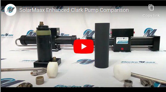
This pump adopts completely different techniques and materials from the Spectra and Schenker ones, which now definitely belong to an obsolete technology. Unparalleled reliability for this new system. Take 4 minutes (only 4!) to watch the video below to get a good understanding of the big differences with other pumps on the market.

clark video 1 - INSTALLATION, OPERATION & MAINTENANCE MANUALS

Thank you for choosing the AquaGate reverse osmosis watermaker, equipped with automatic pressure regulation and the 3rd Generation “Enhanced Clark Pump” energy recovery technology.

Adding a low-energy watermaker to your setup can significantly enhance your cruising experience. With proper use, you’ll no longer need to go out of your way to find expensive or unreliable water sources, nor will you need to haul heavy jerrycans from the dinghy.

The AquaGate is capable of producing enough water for you and your crew to shower daily and can save you money by allowing you to rinse salt from your boat and equipment, reducing both maintenance and replacement costs.

We are confident you will love your new system and are proud to support it with a leading warranty and exceptional customer service.

There are several mistakes that the installer or operator of the AquaGate might make that could severely damage the watermaker, significantly reduce its lifespan, or even result in personal injury. Understanding what to avoid is essential for proper installation and operation of the AquaGate. While these points will be discussed in more detail in the relevant sections of this manual, their importance warrants highlighting them here for special attention.

warning image transparent - INSTALLATION, OPERATION & MAINTENANCE MANUALS
Warning: The AquaGate marine reverse osmosis watermaker is designed to be used in typical sea water. Using taste to test the quality of the product water only works with a sea water feed. Operating in freshwater without sterilizing the product could result in sickness or death.

warning image transparent - INSTALLATION, OPERATION & MAINTENANCE MANUALS
Notice:
Never allow chlorinated water to come in contact with the RO membranes. Oxidants such as chlorine and/or bleach water will destroy the RO membrane.

warning image transparent - INSTALLATION, OPERATION & MAINTENANCE MANUALS
Notice:
Never run the AquaGate marine reverse osmosis watermaker in oily water. Oil will permanently ruin the RO membrane.

warning image transparent - INSTALLATION, OPERATION & MAINTENANCE MANUALS
Notice:
Do not install the RO membrane module in an area where the RO membranes can become heat soaked to temperatures above 113°F/45°C.

warning image transparent - INSTALLATION, OPERATION & MAINTENANCE MANUALS
Notice:
The RO membrane module is shipped already mounted, but it contains a storage/preservative solution which must be purged at system start-up.

warning image transparent - INSTALLATION, OPERATION & MAINTENANCE MANUALS
Notice:
A proper cables section and a good electrical supply to the feed pump is mandatory for proper system operation.

warning image transparent - INSTALLATION, OPERATION & MAINTENANCE MANUALS
Notice:
Never use a 5-micron “carbon” filter in place of the supplied 5-micron prefilter element. Use only 5-micron melt blown filters.

warning image transparent - INSTALLATION, OPERATION & MAINTENANCE MANUALS
Notice:
Only use 1% SMBS as storage chemical solution. Other products may damage the system.

Production Rate: 30 liter per hour, 8 Gallons per hour :
The production rate is set by the displacement of the Enhanced Clark Pump energy recovery device and the feed flow rate. The AquaGate marine reverse osmosis watermaker uses a 10% displacement Clark Pump so 10% of the feed water flow is turned into product water. Water temperature and salinity affect operating pressure but has little effect on production rate. Changes in feed flow does have an effect, the more feed flow the more product. Supplying good voltage to the feed pumps gives the best production rate. Running the system while the batteries are bulk charging gives the highest production rate.

Reverse Osmosis Membranes:
The AquaGate watermaker is equipped with Reverse Osmosis Membrane(s)
Membrane Type: Polyamide Thin-Film Composite
Membrane Model: Seawater 2521
Range of Operating Pressures: 45 to 69 bar (650 to 1000 psi)
Normal Operating Pressure: Set by feed water conditions and feed flow rate.
Salt Rejection rate: 99.4%
Maximum Operating Temperature: 45°C (113°F)
Minimum Storage/Operating Temp: 0°C (32°F)
Maximum Operating Pressure: 69 bar (1,000 psi)
Maximum Pressure Drop: 1 bar (15 psi)
pH Range, Continuous Operation: 2-11
pH Range, short-term cleaning: 1-12
Free Chlorine Tolerance: <0.1ppm
Electrical Power Requirements:
10.0 amps @ 12.5-14.4 VDC

The Enhanced Clark Pump Hydraulic Pressure Intensifier:
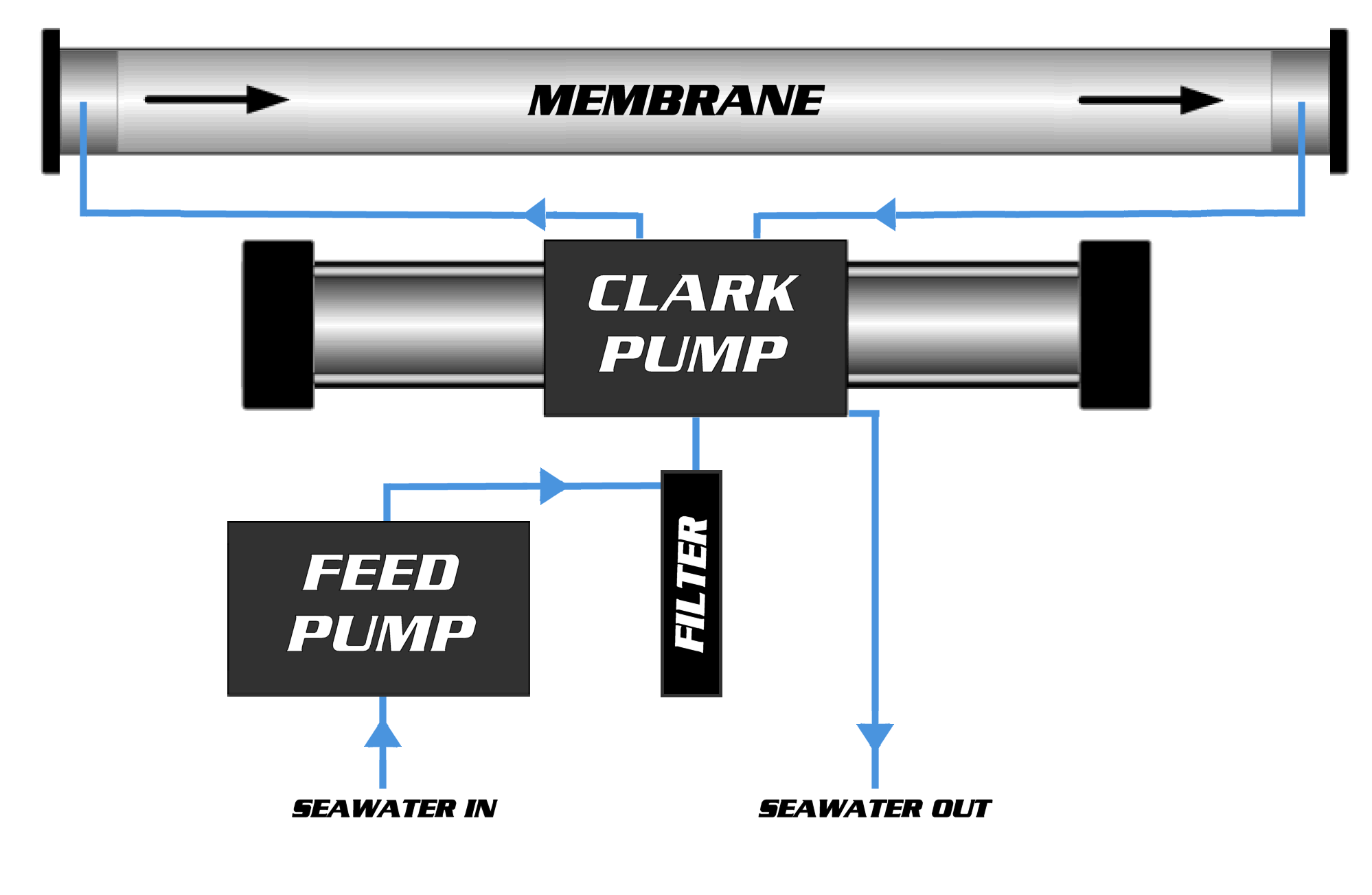
Manufactured by ElectroMaax for marine and military use. The Enhanced Clark Pump uses the Feed
pump flow pressure to intensify the pressure of the flow through the RO membranes high enough for
reverse osmosis to occur. There are no electrical components.
Check out this video, it explains the upgrades and benefits of the 3rd generation Enhanced Clark Pump over similar ones like Spectra or Schenker.

clark video 1 - INSTALLATION, OPERATION & MAINTENANCE MANUALS

Displacement: 10 %
Feed Flow range: 3.78 lpm (1.0 gpm) to 15.14 lpm (4.0 gpm)
Maximum Inlet pressure: up to 8.6 bar (125 psi)
Maximum Working Pressure: 68.9 bar (1000 psi)
Maximum operating temperature: 45℃ (113°F)
Maximum storage temperature: 60.0℃ (140℉)
Pump Dimensions: 67cm (26.38”) W, 14.6cm (5.75”) D, 20.32cm (8.0”) H
Pressure Relief Valve: Manually open ½ turn for priming and servicing

Feed Pump:
Motor: Permanent magnet type, fully enclosed, 300 Watt
Pump Body: Thermoplastic
Pump Type: 3 chamber diaphragm
Typical Amp Draw: 8-10 Amperes @12VDC
Recommended fuse size: 15 amps, 12VDC

Pressure Vessel:
Composite material: fiberglass/epoxy compound with PTFE heads. They combine a really great look with an extreme ease of installation, requiring no high-pressure hose to interconnect each other in multi-membrane systems, thanks to the side ports machined in the heads. Easily demountable for membrane replacement.
Compact movable unit made by high performance composite material, very light and strong. This kind of RO pressure vessel is easy to handle and fit aboard. Designed for a continuous long-term use and for a maximum working pressure of 70 bars. Great, clean and elegant design.
Max continuous operating pressure 70 Bar (1000 psi)
Single 2521 Vessel

Prefilter and Carbon Filter housings:
Industry standard, 10 inch, plastic, filter housings. Accepting 10” DOE filter cartridges.

Control Panel:

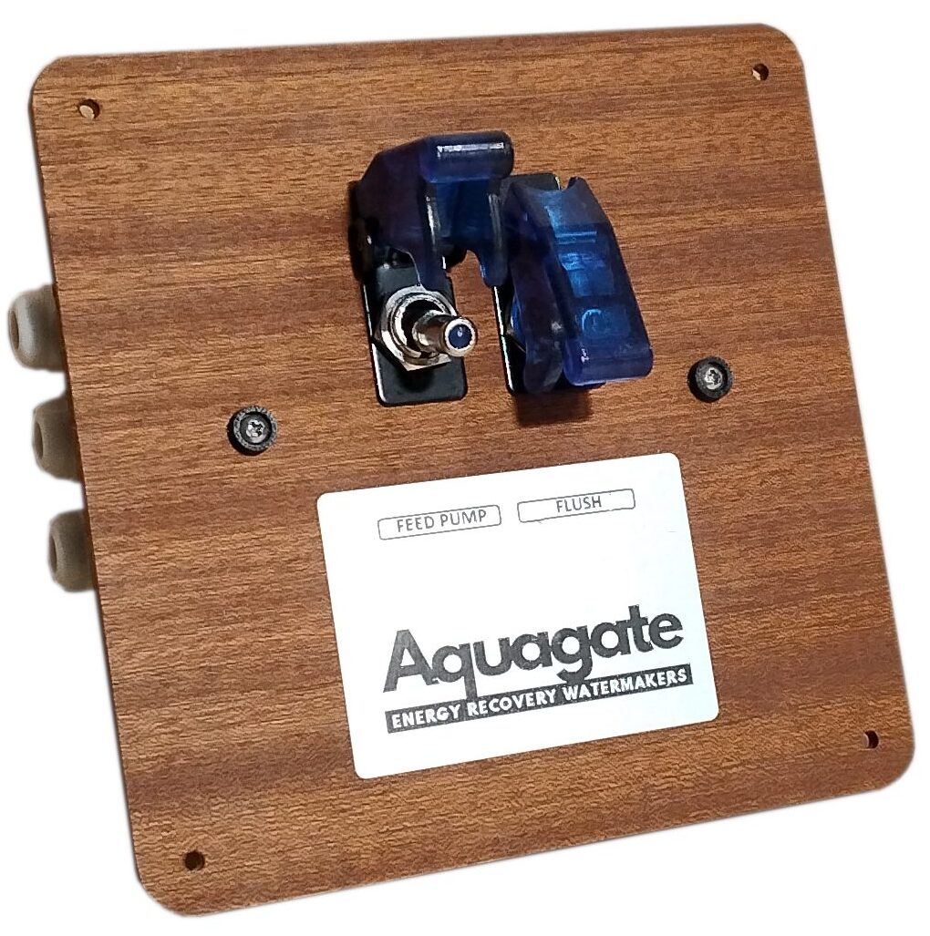
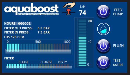
This water maker comes with a very small and simple panel for switching on the feed pump and the flushing solenoid valve. Only one switch is basically needed to run the desalinator, as the working pressure adjusts automatically.
Dimensions: 5.9” (15 cm) W, 5.9” (15 cm) H, 3.9” (10 cm) depth

Clark Pump and Pressure Vessel Assembly, 1-21” Membrane:
Dimensions: 16.3” (41.3 cm) W, 24.7” (62.8 cm) L, 8.4” (21.3 cm) H
1-21” membrane 24.7” (628 mm) L
Weight: 1-21” 30.0 lbs. (14 kg)

The AquaGate marine reverse osmosis watermaker can be purchased with 1 only membrane 2521. It comes with two pieces of two-meter long high-pressure hose that can be cut to length and onto which reusable fittings can be mounted.

The membrane can be mounted horizontally and vertically. If it is to be mounted vertically the water flow must go from the bottom to the top (inlet bottom and outlet top).

Configuration 1 membrane and feed pump - INSTALLATION, OPERATION & MAINTENANCE MANUALS

The AquaGate marine reverse osmosis watermaker is simple to install. When all the components are connected in the right order the system will perform as designed and give all the freshwater you need for a long time. Every install is going to be different in where and how the components are mounted so forethought is necessary for the ideal layout for your installation. If you are already familiar with watermakers without an energy recovery device like the Clark Pump, please try to forget what you know as much won’t apply to this system and may lead you astray. Please read the instructions and don’t make assumptions based on older types of systems.

Mounting the Components without service valves Aquagate

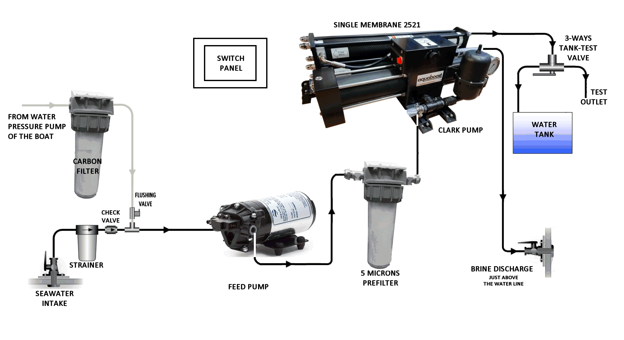
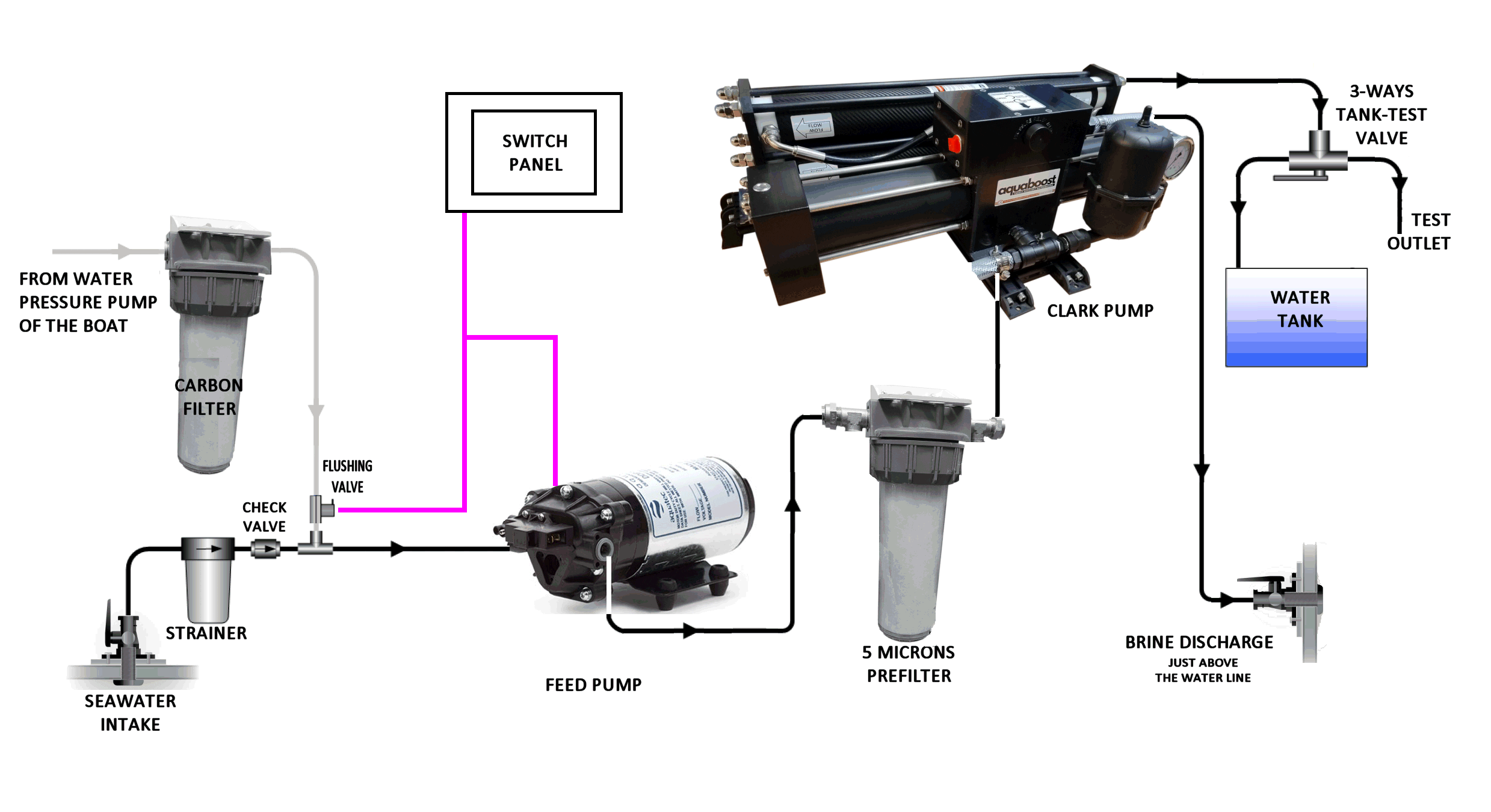
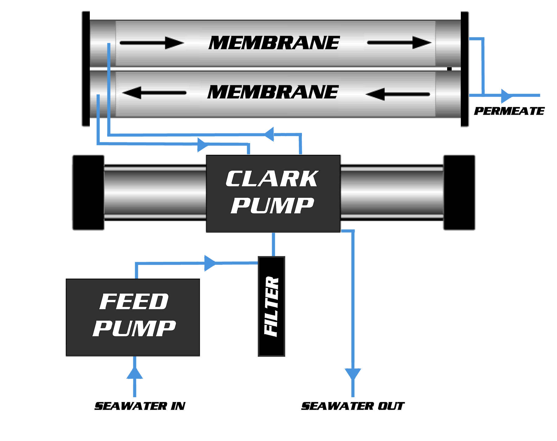
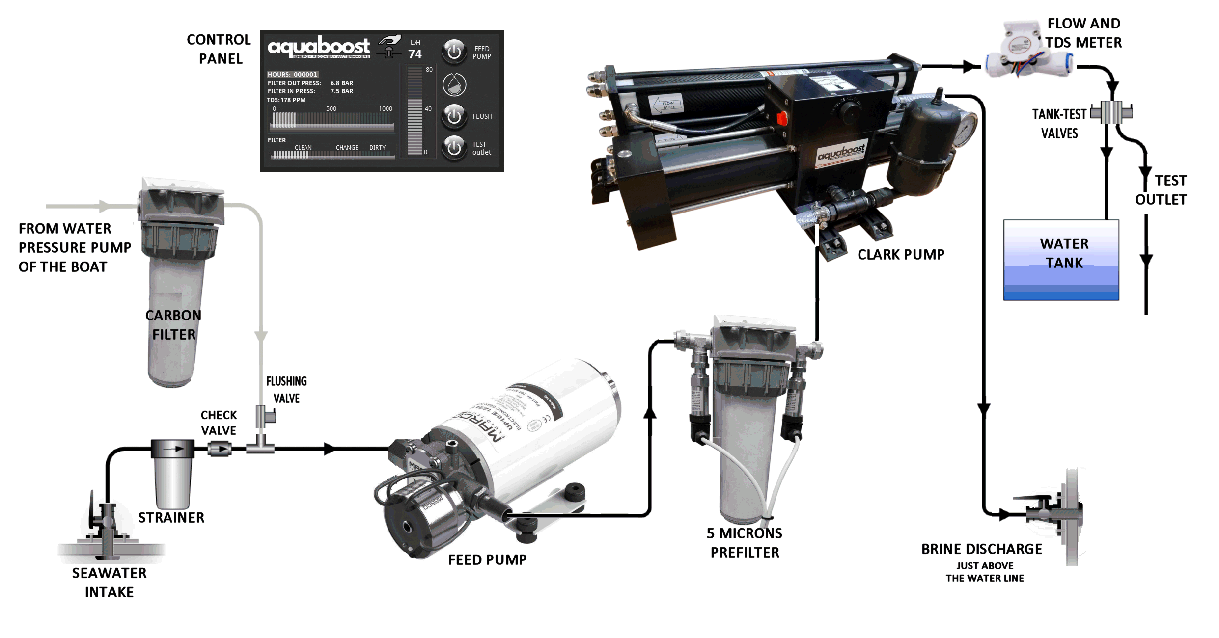
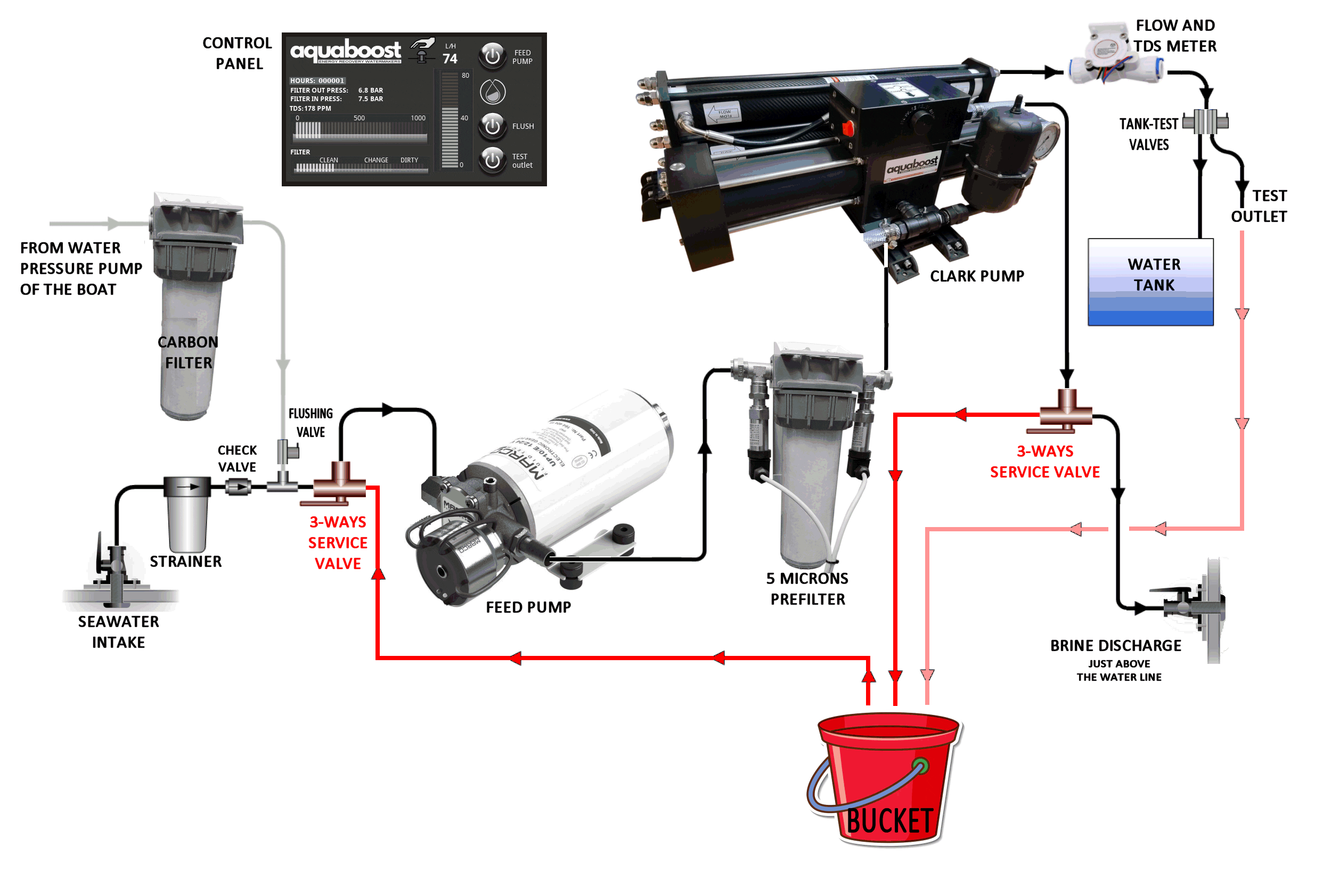
Simplified Component and Plumbing Layout to familiarize yourself with how the major components interconnect.

Before starting the installation process, please read the entire installation guide carefully. Take a moment to review the following installation notes to ensure your AquaGate marine reverse osmosis watermaker performs optimally, lasts longer, and is easy to operate and maintain.

Every boat is unique, so if you have any questions or uncertainties, don’t hesitate to contact us. We’re here to assist you and would rather help you address any concerns now than after the system is installed, with components mounted and holes drilled into your boat.

Installation Notes:

A. When choosing a mounting location, ensure easy access to components requiring regular maintenance, such as the pressure relief valve on the Clark pump, pre-filters, membrane, flush filter, and service valves.

B. The boost/feed pump needs a 15-amp fuse or breaker for 12 VDC systems.

C. Route both high-pressure and low-pressure water lines carefully to avoid chafing or tight bends that could cause kinks and restrict water flow.

D. Use Teflon tape or Loctite 55 sealing cord for water line fittings, avoiding the first thread. Do not use paste-type sealants, as they can enter the system and damage the membrane or Clark Pump.

E. Install the RO membrane in a location where it won’t be exposed to temperatures above 45°C (113°F) when not in use.

F. Good planning and component layout are crucial for a successful installation. Dry-fit the components first to confirm the plumbing layout before securing them in place.

G. Avoid sharp 90-degree fitting turns. A longer tube with smooth bends is more efficient than a shorter tube with hard 90-degree angles, as it reduces flow resistance.

H. Electrical connections should be handled by someone knowledgeable and experienced with 12 and 24 VDC systems.

I. Voltage drop can reduce system performance. Use the recommended wire sizes (or bigger) to ensure proper operation.
Seacock
INTAKE SEACOCK:
Install a dedicated ¾” seacock with a forward-facing scoop, positioned as low and centrally on the boat as possible. Avoid placing it near or downstream from a head outlet or sink drain. It is recommended to have this installation completed by a professional yard during a haul-out. While sharing a through-hull with another system is not ideal, it may be acceptable in specific circumstances. Use 20 mm (not less) hose barbs made from the same material as the valve, along with a reinforced hose rated for below-waterline use, connecting it to the sea strainer. Please note that the seacock and hose are not included in the Aquaboost kit.
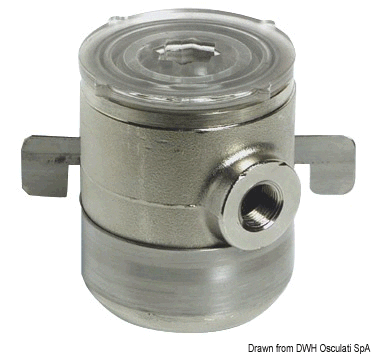
strainer
SEA STRAINER

The Sea Strainer protects the check valves in the feed pump by preventing debris from jamming them. It is installed between the intake thru-hull valve and the feed pump. The ideal location is just above the waterline, though it can also be placed above or below it. To avoid spills during servicing, do not mount the strainer over sensitive equipment.

Use 20 mm (not less), reinforced hose between the intake thru-hull and the Sea Strainer, and double clamp all hose connections. Ensure there is sufficient clearance below the bowl for easy removal. Once you’ve chosen a location, secure the mounting bracket with screws. Check the housing for a directional arrow to confirm the flow direction, then attach the hose and tube fittings through the bracket and into the strainer body. These fittings will secure the strainer body in the bracket.
During servicing, take care not to misplace the bowl gasket. After servicing, ensure the strainer bowl is screwed on tightly to prevent air from entering the system. Please note that the sea strainer is not included in the Aquaboost kit.
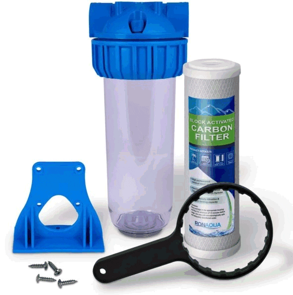
carbon filter
CARBON FILTER FOR FLUSHING WATER
The Flushing function is used to flush the seawater out of the system after use. A carbon filter is installed to remove any chlorine from the ship’s water tank, as chlorine can damage the membrane. Mount the filter vertically using the built-in mounting bracket, ensuring at least 5 cm of clearance below the assembly to allow easy access for opening the filter housing.
Note that fresh water will spill during filter replacement.

The inlet of the filter is connected to the ship’s pressurized water system using owner-supplied hose or tubing and a Tee-fitting that matches the ship’s plumbing. The outlet from the flush filter is connected to a Tee installed in the feed line before the feed pump. Replace the carbon filter every 6 months of use or whenever the system comes out of long-term storage.
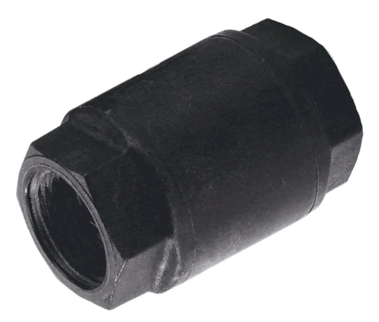
amita - INSTALLATION, OPERATION & MAINTENANCE MANUALS
CHECK VALVES

The Flush Check Valve prevents pressurized, filtered flush water from flowing back out through the intake thru-hull and ensures it is directed to the Feed Pump. For optimal performance, the valve should be installed as close as possible to the Flush Tee to avoid any saltwater sitting between the valve and the Tee.
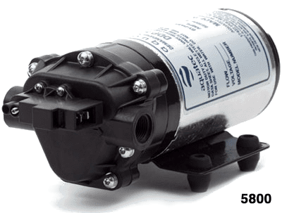
Aquatec pump - INSTALLATION, OPERATION & MAINTENANCE MANUALS

FEED PUMP
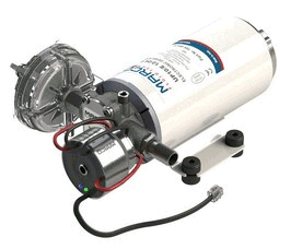
The Feed Pump Assembly is a 3 chamber diaphragm type automatic pressure pump . These pumps are similar to the marine ones but their delivery and pressure are specifically designed for this application. There is no need to adjust the pressure, and these pumps are self-priming (max. -1,5 meters). Have enough space around it to dissipate the heat and only if needed, place vents below and above the pumps to allow for convection currents to take away the heat.
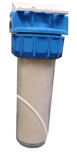
Filter without Sensors e1734251649421 - INSTALLATION, OPERATION & MAINTENANCE MANUALS
PREFILTER

A single 5 microns prefilter is supplied with the water maker.
Use only melt blown and never wire wounded cartridges!
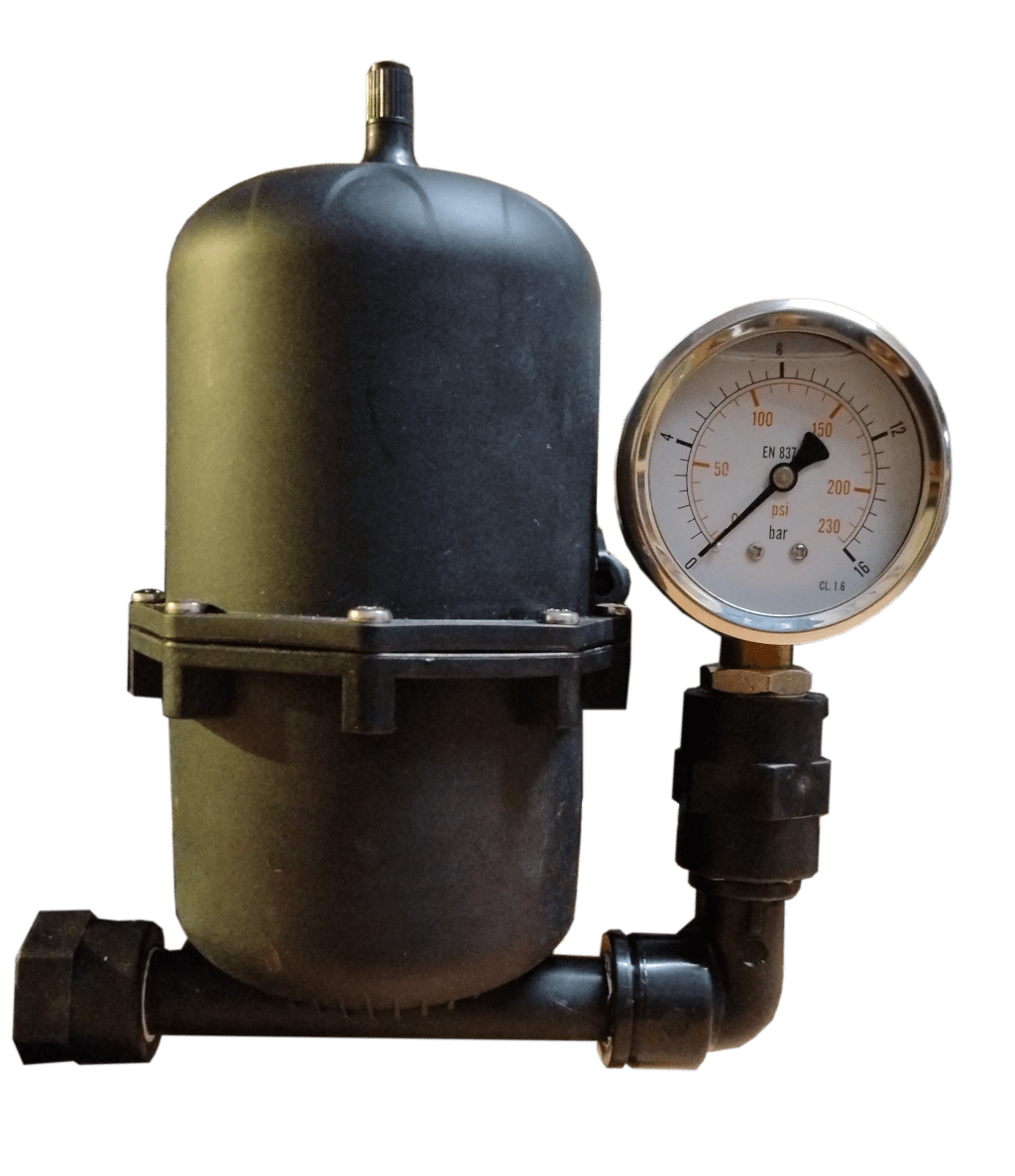
Gauge
ACCUMULATOR TANK WITH PRESSURE GAUGE

The Accumulator Tank must be pressurized to 4 bar (60 psi) before use. It is used to smooth out the feed flow to the Clark Pump when it “shifts” and reverses direction internally. It absorbs pressure spikes during a shift which can affect the pressure switch on the Feed Pump. Use a bicycle pump to fill to a higher pressure, and then use an accurate tire pressure gauge to set it to 60 psi. If the Clark Pump shifts are affecting the Feed Pump, check the pressure while the system is off, and the Pressure Relief Valve on the Clark Pump is open. The accumulator tank and the pressure gauge are provided already mounted on the inlet of the Clark Pump.
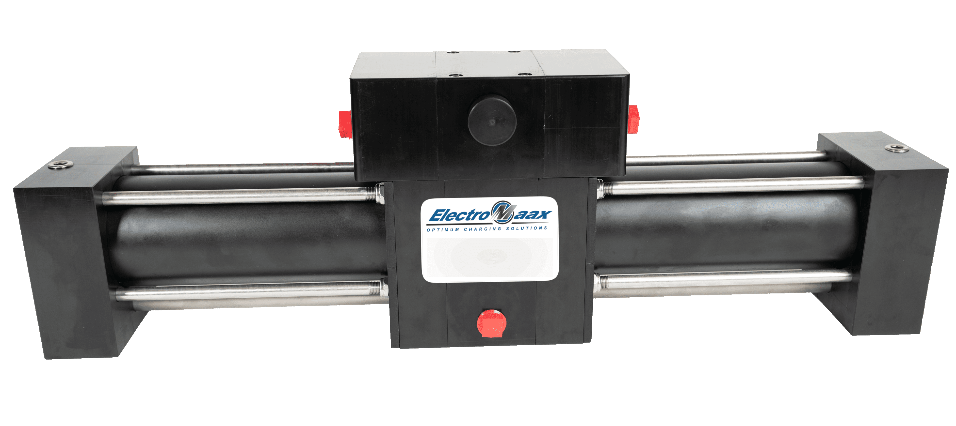
Clark Pump - INSTALLATION, OPERATION & MAINTENANCE MANUALS

3rd GENERATION ENHANCED CLARK PUMP
The Clark pump and the vessels with the membranes are mounted on an aluminum frame and only need to be connected to:
– Prefilter (use 20mm diameter pipe, no smaller)
– Overboard discharge (concentrated, use 20mm diameter pipe)
– Permeate pipe to freshwater tank (provided in kit).
No electrical connection is needed.

The Clark Pump has two brine discharge ports to choose from. Both are plugged at the factory for shipping. Remove the plug from the one that best suits the plumbing arrangement and leave the other side plugged. The Pressure Relief Valve is all plastic and is only finger tightened. Do not over tighten. Leave the Pressure Relief Valve open ½ turn for the initial commissioning.
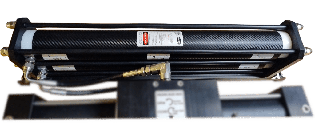
Membranes assembly
PRESSURE VESSEL AND RO MEMBRANE ASSEMBLY

The pressure vessel (1x 2521) comes with the membrane already inserted and are ready for commissioning for the first time. It is recommended that the machine be commissioned within a maximum of one month after delivery.
The pressure vessels assembly and the Clark pump have a base/brackets to be easily mounted aboard. Our reverse osmosis RO pressure vessels in composite are the best product in this segment. They combine a really great look with an extreme ease of installation, requiring no high-pressure hose to interconnect each other in multi-membrane systems, thanks to the side ports machined in the heads.

switch - INSTALLATION, OPERATION & MAINTENANCE MANUALS
SWITCH PANEL
The water maker is driven from a small and very simple panel, containing two switches with LED and transparent safety cover. One dedicated to the feed pump, and the other one to the solenoid valve for flushing the system.
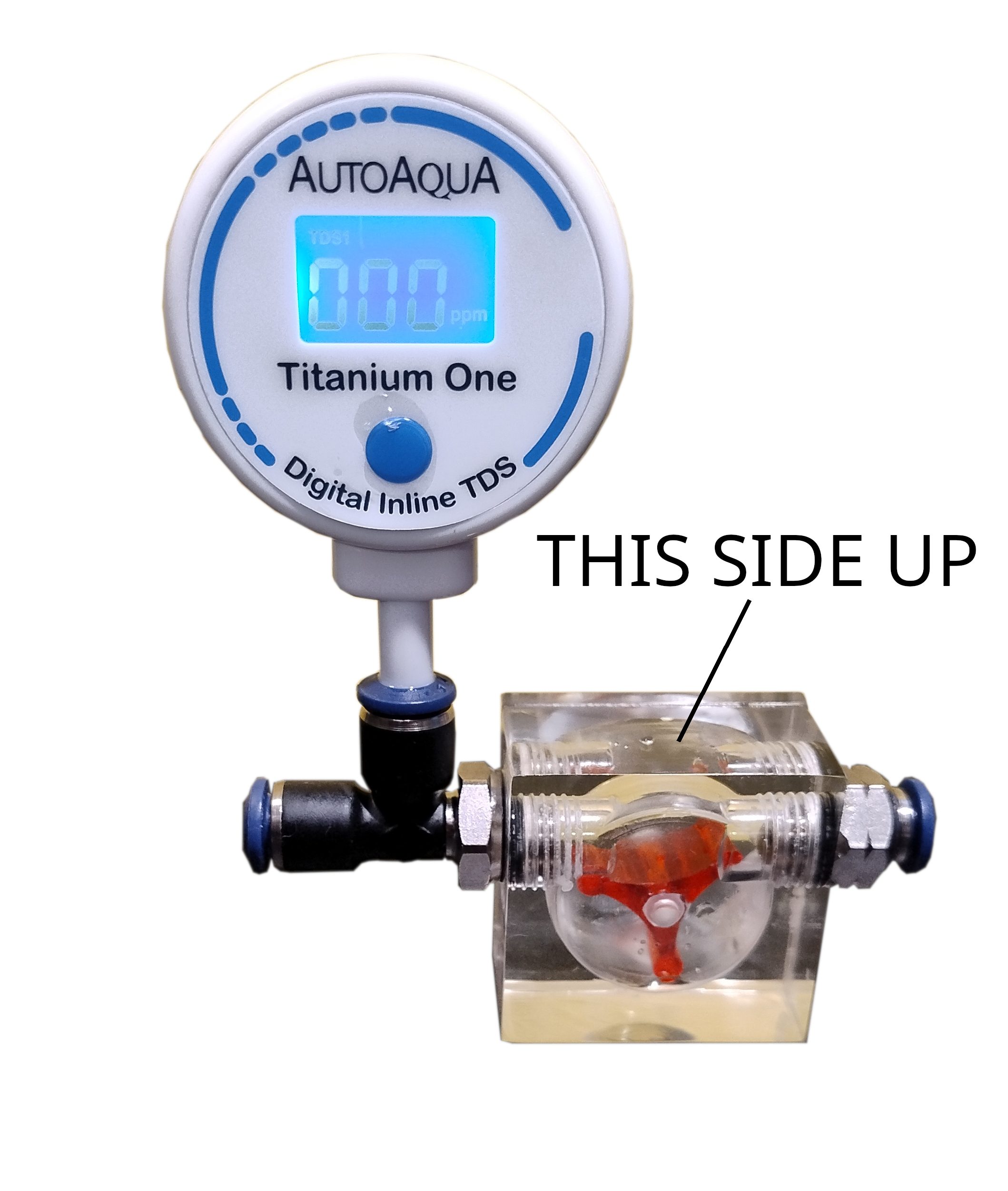
flow indicator autoaqua
TDS and FLOW INDICATOR

In this entry level Energy Recovery Watermaker a flow indicator is supplied together with our inline TDS meter.
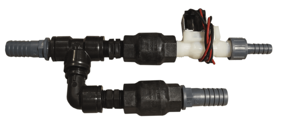
easy flushing

EASY FLUSHING SYSTEM
It is mounted on the activated carbon filter and allows flushing of the system at the end of the fresh water production cycle. It is connected to a simple switch that opens the solenoid valve.
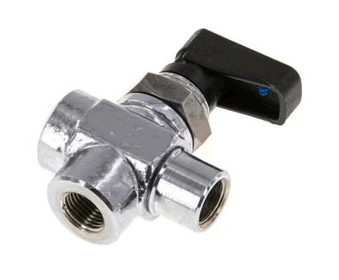
3-way valve

TANK/TEST 3-WAY VALVE
A small 3-way valve is supplied with the water maker. It is used to divert the freshwater flow to the tank or to a test outlet.

3-WAYS SERVICE VALVES
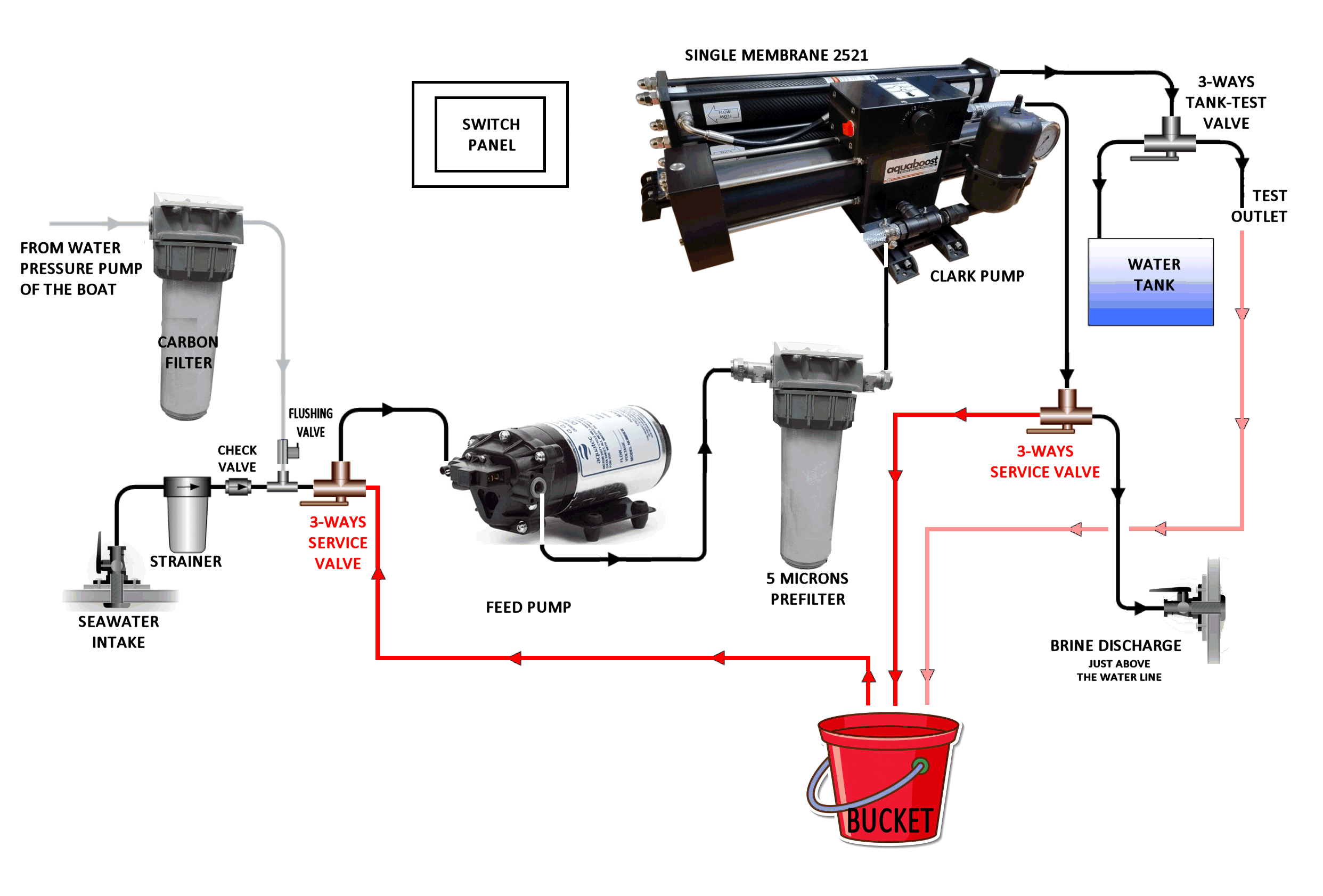
These two 3-way ball valves (L-operating) are used to carry out long term storage of membranes or their cleaning with chemical preparations. They are not supplied with the water maker, but the customer can decide to mount them himself. In any case, we recommend using our valves kit for cleaning/preserving/pickling the membranes instead.

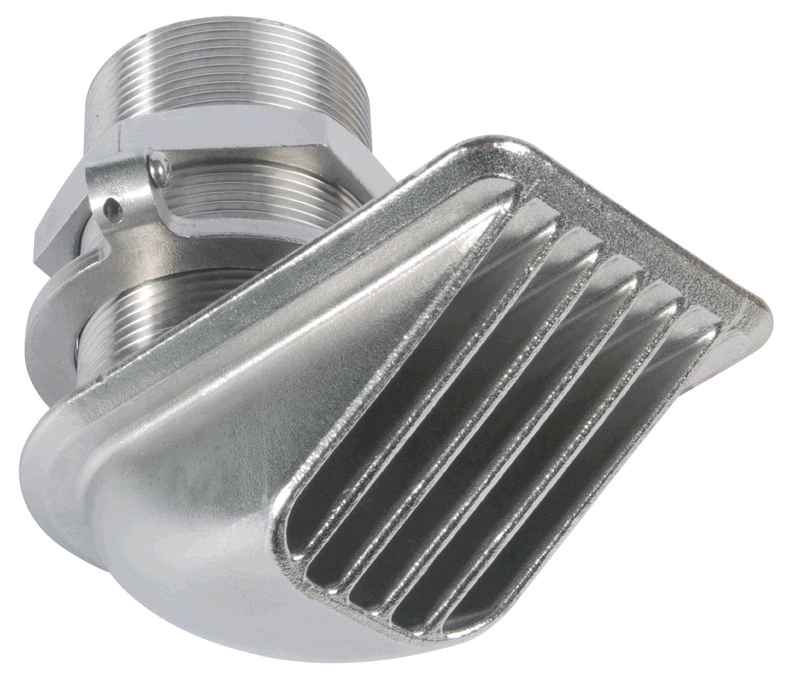
DISCHARGE THROUGH HULL
The Owner must provide and install a 1/2” or 3/4″ hull fitting just above the waterline. It is possible to tee it into an existing drain above the waterline but there is a good chance it will cause gurgling noise and flood the boat if the drain through hull valve gets closed. For those reasons, it is highly recommended to install a dedicated through hull for the watermaker

A.
First, refer to the component size tab to identify the spaces on board, where to install the water maker.
B.
Follow the flow diagram and the mounting notes in the component descriptions. Note how the 3-way valves are plumbed, they will always introduce a 90° turn in the flow.
C.
When mounting the components, check the thickness of the bulkhead and cabinet panels and size the fasteners appropriately. If using through bolts, use Nylock nuts and washers. Use fasteners that match the mounting holes in the components or one size under at most.
D.
The length of the feed and discharge tubes do not affect the performance, but many right-angle turns will. Long sweeping turns are better.
E.
Place the Clark Pump/Pressure Vessel assembly for easy access to the pressure relief valve while operating the system and with consideration for how to replace the membrane which means either there is enough room off one end of the Pressure Vessel to remove the membrane in place or the Pressure Vessels needs to be removed to allow access. Allow wrench access to the High-Pressure fittings at the ends of the membrane for removal. The HP fittings require 2 wrenches for assembly or removal. The flexible HP hoses and the swivel fittings in the Clark Pump allow for installation options for fitting access.
F.
The 3-way Service Valves (if mounted by the customer) should be located in the same area where a Service Pail can be securely placed, and the Service Tubes can all reach it at the same time. This is important for ease of use and maintenance. The Service Tubes can be removed or tucked away when not in use.
G.
Place the panel in an area that has easy access.
H.
The Product water must be dropped into the top of the tank without any back pressure. Do not connect it at the bottom outlet of the tank as the head pressure may try to push product water backwards through the membrane. Tee into the tank vent line or add a port into the top of the tank.
I.
Make sure the tank vent is not clogged. If the tank is overfilled, the product will flow harmlessly out the vent.
J.
The Feed Pump Assembly should be mounted to a rigid horizontal surface in a dry area below the waterline or up to 1 meter above the waterline. Best is at or below the waterline. It can also be mounted vertically, in which case place the pump body under the motor

Mounting the Components without service valves Aquagate

Components mounted without the 3 ways service valves (the system uses our valves kit for cleaning/preserving/pickling the membranes).
We suggest this kind of installation.


Mounting the Components with service valves Aquagate

Components mounted with the 3 ways service valves (the system does not use our valves kit for cleaning/preserving/pickling the membranes).

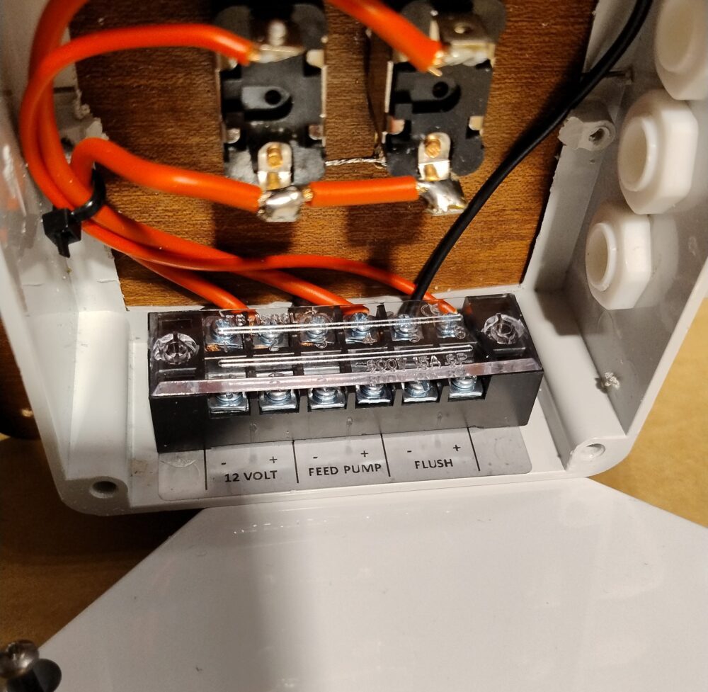
Proper wiring is important to minimize voltage drop between the batteries and the Feed Pumps. Use Marine grade tinned multi strand wire. Pick one of the methods above, taking power from a breaker on the panel or wire an inline breaker directly from the house batteries, whichever is closer. Use cables of 4 mm2 cross-sectional area (or larger). Try to keep connections as short as possible. Using cables that are too thin or too long with inadequate diameter has a negative impact on pump performance. The panel connectors are marked and it is not possible to connect them incorrectly

Mounting the Components Electrics Aquagate

The Commissioning Procedure should be performed at a new system start up. The main function is to prime the Feed Pump, look for leaks, and purge the system of the chemicals used for the storage of the membranes.

  1. Open the watermaker intake and discharge through hull valves.
  2. Open the Pressure Relief Valve 1/2 turn from a finger tight closed position.
  3. Remove the inlet pipe of the Clark Pump and send it to a bucket or sink.
  4. Turn the flushing switch ON
  5. The flushing is started. Let it run for 3/4 minutes. In this way you purge the air from the carbon filter and part of the circuit.
  6. Look for leaks in the system. If any leaks are found, turn off the switch and repair it before continuing. You will need to see water coming out from the hose.
  7. If needed repeat the procedure. This one-time step clears any debris between the Prefilter and Clark Pump.
  8. Reassemble the inlet pipe to the Clark Pump
  9. Take care that the permeate goes to the test outlet and not to the tank and then turn the switch of the pump ON.
    Look for water flowing through the Inlet Strainer. When the feed water reaches the Feed Pump, its sound will change and be uneven then smooth out as the air is purged. Pressure will start to build in the feed pressure gauge and the Clark Pump will make its first “shift” at it starts to circulate water through the membrane. The shifts should start to even out as the air is purged. They may be hard to hear, watch for a rise and fall of boost pressure as the Clark Pump shifts.
  10. With the Feed Pump running, make a visual inspection to ensure that the connections are all leak free. If any leaks are found, turn off the system and repair it before continuing.
  11. Continue to run the system unpressurized (Pressure Relief Valve open) for 15/20 minutes to purge the storage solution from the membrane elements. The Feed pump should be running smoothly now. If not, there is an air leak in the Strainer or Flush systems. Fix before continuing.
  12. After 15/20 minutes and the system is running smooth with regular shifts in the Clark Pump, close the Pressure Relief Valve. The sound of the Feed Pump and the Enhanced Clark Pump shifts will change as high pressure is generated in the Membrane and within a short time  the product water will start to flow through the flow indicator and then out from the Test outlet.
  13. Check for leaks at the high-pressure hose connections and around the Clark Pump, Membrane end fittings and Control Panel. Recheck the Feed system for leaks. If leaks are found, stop the unit, and correct as needed.
  14. Run the system with the Product Water diverted for 10 minutes to purge the Product Water side of the Membrane to clear any remaining Storage Chemical.
  15. Check the water quality with the TDS meter and if the TDS meter shows a value below 500 ppm, switch the permeate flow to fill the tank if desired.
  1. Open the watermaker intake and discharge through hull valves.
  2. Open the Pressure Relief Valve on the Clark Pump 1/2 turn or, if the system has been recently run and is well primed, the Pressure Relief Valve can remain closed.
  3. Take care that the permeate goes to the test outlet and not to the tank and then turn the switch of the pump ON.
    Listen for the Feed Pump to run smoothly and the Clark Pump is shifting normally.
  4. Close the Pressure Relief Valve finger tight (if opened). Watch for water flow through the flow indicator.
  5. Check the water quality with the TDS meter and if the TDS meter shows a value below 500 ppm, switch the permeate flow to fill the tank if desired.
  6. If the water tank overfills, the water will overflow out the vent but should not cause a problem.

NORMAL RUN

  1. Watermakers like to run. The best practice is to run until the tanks are full, shut down with a freshwater flush, then restart when the tanks are down after a few days. Flushing is important because biological growth that can happen inside the membrane in saltwater will not survive in freshwater and vice versa.
  2. Monitor the Filter Status. Filter elements clean better if they are cleaned as soon as they start, or even better, before they start to restrict the flow.
  3. Oil in a membrane will ruin it. It’s usually not a problem as oil normally floats on the surface but if an oil slick is encountered at sea in rough conditions it can get into the system. Avoid running the system.
  4. The system can be run from a brackish or freshwater feed source without having to make any adjustments. A good membrane works equally well in fresh or salt water. The feed pressure will be lower operating in freshwater.

WARNING: The TDS is not 100% reliable when operating with freshwater feed. If the membrane is damaged enough to let a pathogen through it will show up as very high TDS in the product water while operating in salt water but not in freshwater!!

NORMAL SHUT-DOWN, NO FRESHWATER FLUSH:

  1. Turn off the system with the Pump Power buttons on the Panel
  2. The Pressure Relief Valve can be left closed.
  3. Do not leave the system unflushed for more than a day without running.
  4. A water maker is happiest running for a long time then flushed every time it’s turned off but there are times where it shouldn’t be flushed. Flushing can uses up to 20 liters of freshwater so flushing every time after short runs uses up most or more of the water just made. Being used every day, fouling is minimal so our suggestion is to use the water maker daily and do a flush every 5 days or so.

NORMAL SHUT-DOWN, WITH FLUSH:

  1. Turn off the system with the Pump Power buttons on the Panel
  2. Make sure the ship’s Freshwater Pressure System is on, with plenty of water in the tank.
  3. Simply turn the flush switch on.
  4. Watch for the Feed Pressure to drop and stabilize at a lower pressure as the salt water is flushed from the membrane. If the Feed Pressure remains steady, the flush is not working. Check if the freshwater pressure is functioning, Flush Valve wire connections are good, and the carbon filter isn’t clogged.
  5. Flushing can be done either with the pressure relief valve closed or open.
  6. A trick for determining the flushing time:
    Disconnect the reject hose from the Clark pump and send the flushing water into a bucket. Taste the water coming out at intervals, when it is no longer salty it means the system has been properly flushed and there is no more salt water in it. Make a note of the elapsed time and in the future flush the system for this time without the need to disconnect the reject hose anymore.
  7. Turn off the flushing switch after the desired time.

Membrane Storage Procedure

The composite polyamide type of the membrane elements must NEVER be exposed to chlorinated water. Any such exposure will cause irreparable damage to the membranes. Absolute care must be taken following the preparation of cleaning or storage solutions to ensure that no trace of chlorine is present in the water. Use ever distilled water or permeate water to carry out the operation.
The storage procedure is divided in three chapters, based on the duration of the storage:

  • Short-term storage of the membrane elements in place in the vessels.
  • Long-term storage of the membrane elements in place in the vessels.
  • Dry storage of the membrane elements as spares or before assembling a watermaker.

Short-Term Storage (Maximum 30 days)

Short-term storage is for periods where the watermaker must remain out of operation for more than five days, but fewer than thirty days, with the membranes in place.

  1. Flush the watermaker with de-chlorinated water, following the procedure described in the tab above.
  2. Reflush as described above at 5-day intervals.

Long-Term Storage (Maximum 6 months)

Long-term storage is for periods where the watermaker must remain out of operation for more than 30 days with the membranes in place.

  1. Flush the watermaker with permeate water or in any case with de-chlorinated water
  2. Mount our valves kit for cleaning/preserving/pickling the membranes:
  3. Remove the high pressure hoses from the inlet and the outlet of the membrane rack. ALWAYS USE TWO WRENCHES TO CARRY OUT THE OPERATION!
  4. Mount the two valves as shown in the images and tighten them using two wrenches.
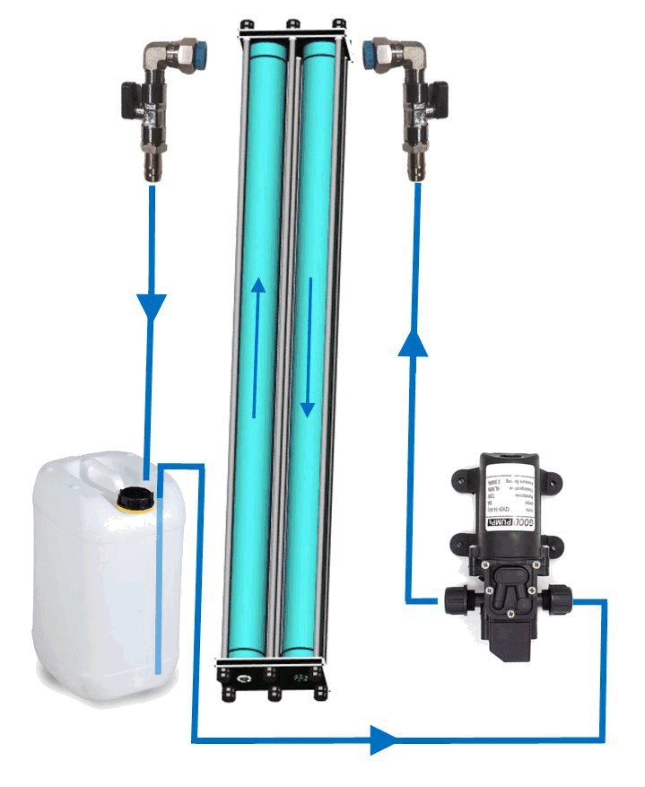
  5. Connect the hose to an automatic cheap pressure pump and to a 10 liters canister where you will prepare the preservative solution. You have created a closed loop.
  6. Prepare 10 liters of solution following the instructions of the producer. Keep in mind that:
    Every 2540 membrane contains 1.5 liters of water and every 2521 membrane contains about 1 liter of water.
  7. Wire the pump to a 12 Volt source, open the valve at the outlet of the membrane rack and then open the valve at the inlet. The pump will start.
  8. Recirculate the solution for a few minutes.
  9. Close the valve at the outlet of the membrane rack and soon after the valve at the inlet.
  10. The vessels are now filled with preservative solution and no bubble of air should be inside. Check for drops/leaks. Flush the cheap pressure pump with some freshwater.
  11. When the watermaker is ready to be returned in service, remove the valves, clean them, reconnect the high pressure hoses, flush the plant and then start it. Discard the water produced in the first 30 minutes.
    With this system the solution does not flow through the other components of the watermaker and the two valves ensure that the system does not empty or air enters.

pickling drawing

If the customer has decided to install the three-way valves for servicing, he can perform the operation using the feed pump and leaving the pressure relief valve open. He will have to position the valves so that the system drains and sucks the solution from the tank or bucket in which it was prepared.

Storage before installation

When RO elements are stored prior to installation, they should be protected from direct sunlight and stored in a cool, dry place with an ambient temperature range of 5°C to 35°C New Elements are enclosed in a sealed polyethylene bag containing a storage solution, and then packaged in a cardboard box.

Note: we have a quite big turnover of membranes, so they are never old. We recommend to use the new membranes within one year from the purchase, and in any case not to keep them on board as spares. By the time you go to use them they will probably have gone bad. Membranes are standard size and can be found almost anywhere. We ship them worldwide and they are delivered within a few days.

CLEANING WITH CHEMICALS

The procedure described above can also be used to flush membranes with chemicals:
Keep the following in mind:
Follow the product manufacturer’s instructions for preparation and always use dechlorinated water.
Use the products separately, one after the other, making a rinse with clean, dechlorinated water between the two. Never mix the products. Always use personal protective equipment!

It is highly recommended to use our valves kit and prevent chemicals from passing through the Clark pump.

5 MICRON PREFILTER

The Clark Pump and the RO Membrane must only operate on 5 Micron filtered Feed Water.

Use only melt blown type filters and never reuse a filter after it has been removed from the container, even just to “take a look”.

Do not use activated carbon filters in the 5 micron filter housing!!! They can let off carbon “fines” with first use. These fines will ruin the Clark Pump and void the warranty.
Do not use washable filters, as they may be accidentally damaged during washing. If they are damaged, their efficiency will be compromised and the warranty for the pump will be voided. Always use disposable polypropylene melt blown type filters with a filtration efficiency of at least 85%

The Filter Status Gauge will tell you the condition of the filter while operating. It is recommended to change the filter before it gets to the red zone. You must take note of the system pressure value with new filter and replace it when this value decreases by 10/20% approximately.

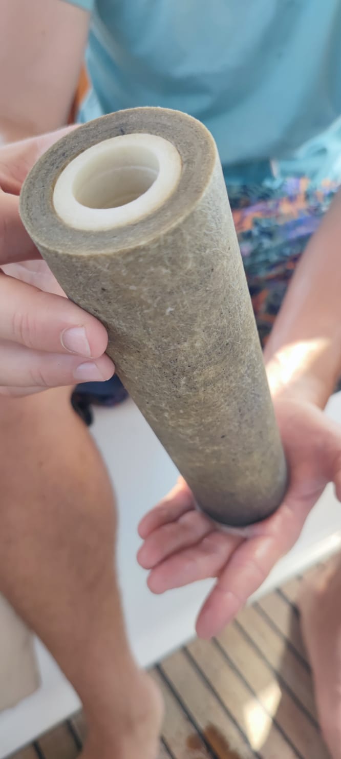
The service life of the filter elements is closely related to the type of inlet water. When you remove the filter, you may notice that the color of the outer part of the cartridge is greyer than the inner part. The filter cartridge should never turn completely grey, it should be replaced before this happens.

Filter to be changed

  1. Loosen union nut of the housing completely using the wrench and remove the bowl downwards.
  2. Empty the bowl in a bucket and remove the used cartridge.
  3. Wash the bowl.
  4. Insert the new cartridge into the bowl.
  5. Grease the O-rings of the bowls with silicone grease. This facilitates the mounting.
  6. Insert the bowl and fasten it with the union nut by tightening it with the wrench.

ACTIVATED CARBON FILTER

During the flushing, the activated carbon filter protects the reverse osmosis membranes from chemical elements, such as chlorine, which would destroy them. Replace this filter at least every 4/6 months.
Follow the same procedure as described above.

This optionally supplied filter must be inserted into the pipe leading to the tank.
Its function is to stabilize the pH of the permeate and make the taste of the water more pleasant in case it is used for human consumption.
Before it is installed, it should be rinsed for half an hour with tap water. Thereafter it should not be replaced. It works even if the level of the dolomite inside drops. A dolomite bag is provided to eventually restore the level.

The use of this filter is especially recommended if only osmosis water is fed into the tanks and they are never filled with marina tap water.

The following applies generally to all desalination plants. In desalinators with a Clark pump, it is not possible to adjust the pressure, which is automatically managed.

Reverse osmosis watermakers are sophisticated systems that demand meticulous upkeep. When product water flow decreases or TDS levels rise, some boaters who are out cruising are quick to blame the membranes. However, as we explain below, there are various plausible explanations for lower (or higher) product flow rates and TDS increasing.

Feed Water Temperature:

You can quickly gauge the feed water temperature by using a basic thermometer (the thermometers in boat instrumentation are often inaccurate)
The feed water temperature has a notable impact on the flow rate of your product water. With reverse osmosis systems being rated based on feed water conditions of 32,000 ppm, 25°C (77°F), and operating at 55 bar (800 psi), it’s crucial to understand the effect of temperature on product water:

As the temperature increases, you can expect a higher TDS and a greater product flow rate. Conversely, a decrease in temperature results in lower TDS and a lower product flow rate. For instance, at 32°C (90°F), you may produce approximately 25% more water, whereas at 10°C (50°F), you could expect a 50% decrease.

In summary:

  • As Temperature Increases you get:
    – Higher TDS
    – Higher product flow rate
  • As Temperature Decreases you get:
    – Lower TDS
    – Lower product flow rate

Feed Water Salinity:

You can measure feed water salinity easily with a refractometer. A refractometer is a simple-to-use device that utilizes light to measure salinity. If you don’t have a refractometer, you can consult this page that reports salt concentrations in all the seas.
You can see that the salinity of the Mediterranean Sea is among the highest globally (about 38000 PPM), while it is much lower in the North Atlantic and Baltic Sea. There is also a significant difference between the east and west coasts of the U.S.

Effect of Feed Water Salinity on Product Water:
The salinity level of feed water has a notable impact on the flow rate of product water. When the salinity is increased, the total dissolved solids (TDS) in the product water also increase, and the flow rate decreases. Conversely, when the salinity is decreased, the TDS in the product water decrease, and the flow rate increases.

If the feed water has a salinity level of 35,000 ppm, you can anticipate a reduction of approximately 10% in the amount of product water. On the other hand, if the salinity level of the feed water is 25,000 ppm, you can expect a boost of approximately 25% in the amount of product water.

In summary:

  • As Salinity Increases you get:
    – Higher TDS
    – Lower product flow rate
  • As Salinity Decreases you get:
    – Lower TDS
    – Higher product flow rate

Influence of Feed Pressure on Output Water:

Membrane test conditions are set at 55 bar, but you can safely work at 60 bar. Don’t forget, however, that going from 55 to 60 bar increases the load on the pump motor by 10 percent, and consequently the current required and the heat that the motor must dissipate also increases.
So if you can work at 55 bar, be happy with that and do not put unnecessary stress on the motor, which is usually located in an engine room or in a confined space where the ambient temperature is already high and ventilation may be poor.

In summary:

  • As Pressure Increases:
    – TDS is reduced
    – Product flow rate is increased
  • As Pressure Decreases:
    – TDS is increased
    – Product flow rate is decreased

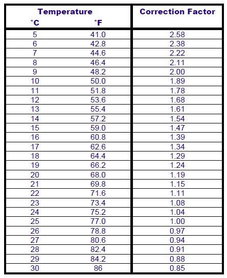
CORRECTION FACTOR TABLE

Divide the productivity by the correction value at the given temperature.
Example for a 100 l/h water maker operating at 20 Celsius degrees:
100 : 1.19 = 84
A 100 l/h water maker will produce approx. 84 l/h if the feed water is 20 degrees instead of 25 degrees.

Correction factor

The following applies to all our reverse osmosis pressure vessels. The colour of the pressure vessels coupled with the Clark pump are black instead of blue, and the heads are made in Teflon.

IMG 20240430 144146102 - INSTALLATION, OPERATION & MAINTENANCE MANUALS

The reverse osmosis pressure vessels in composite by CobrAm are the best product in this segment. They combine a really great look with an extreme ease of installation, requiring no high-pressure hose to interconnect each other in multi-membrane systems, thanks to the side ports machined in the heads.

Our pressure vessels can accommodate any standard 2.5”×21” and 2.5”×40” seawater reverse osmosis membranes.
The end plugs are are machined with a CNC milling from a bar of AISI 316L stainless steel for the maximum in corrosion resistance (Teflon in the models with Clark pump).
The tie bars are as well made of stainless steel, covered with a black PVC duct.
The pressure pipe is coated with a special blue protective film (black in the models with Clark pump).
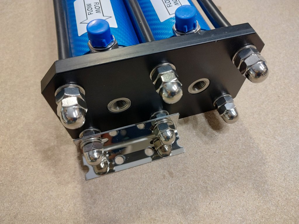
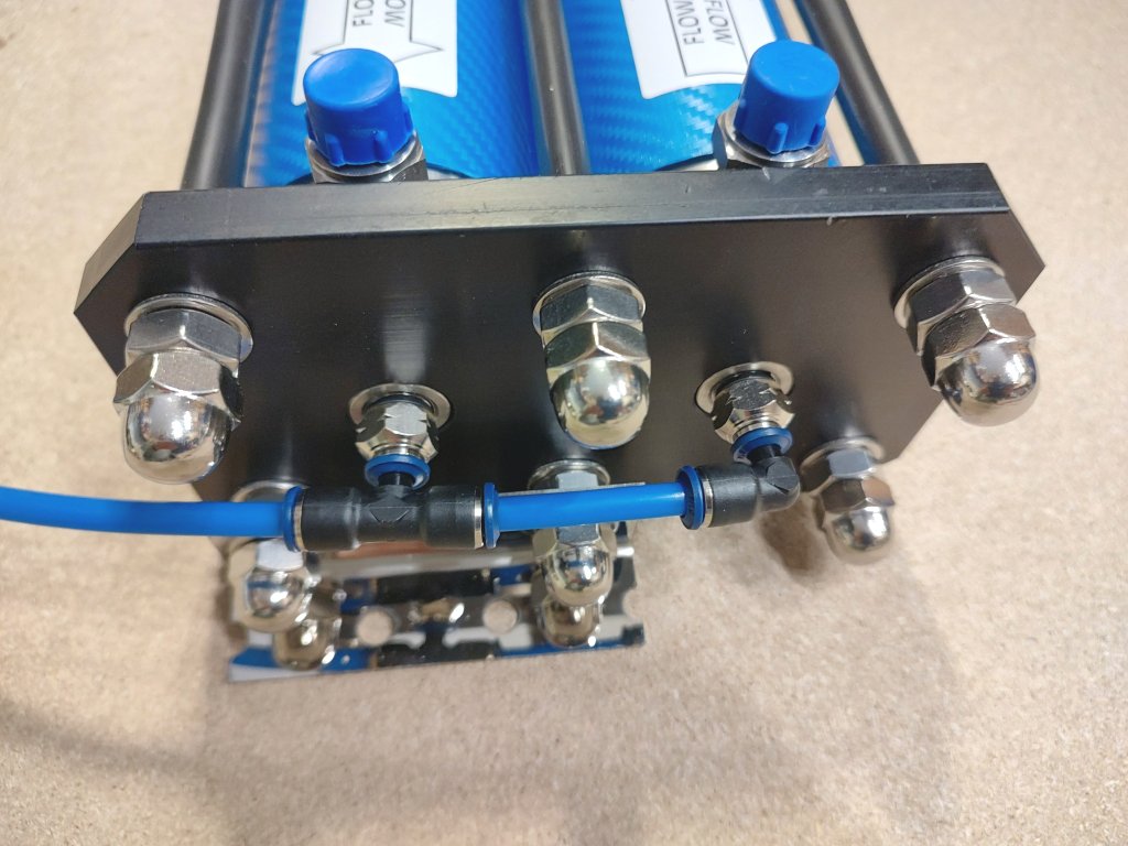
A pair of stainless steel angle brackets are supplied to fasten the vessels to a floor or to a bulkhead.

In our watermakers the vessels come ready-made with the membranes mounted inside, but we also sell the vessels as spare parts, so it is explained here how they are made and how to insert the membranes.


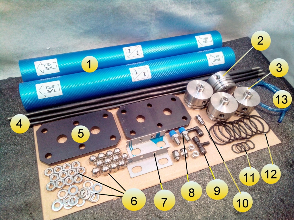
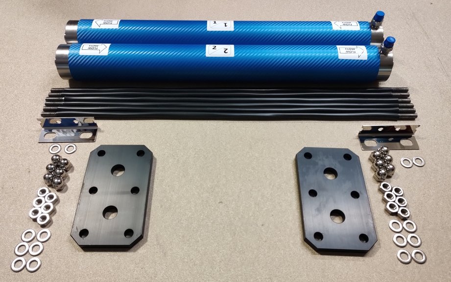
Parts of the Vessel Rack

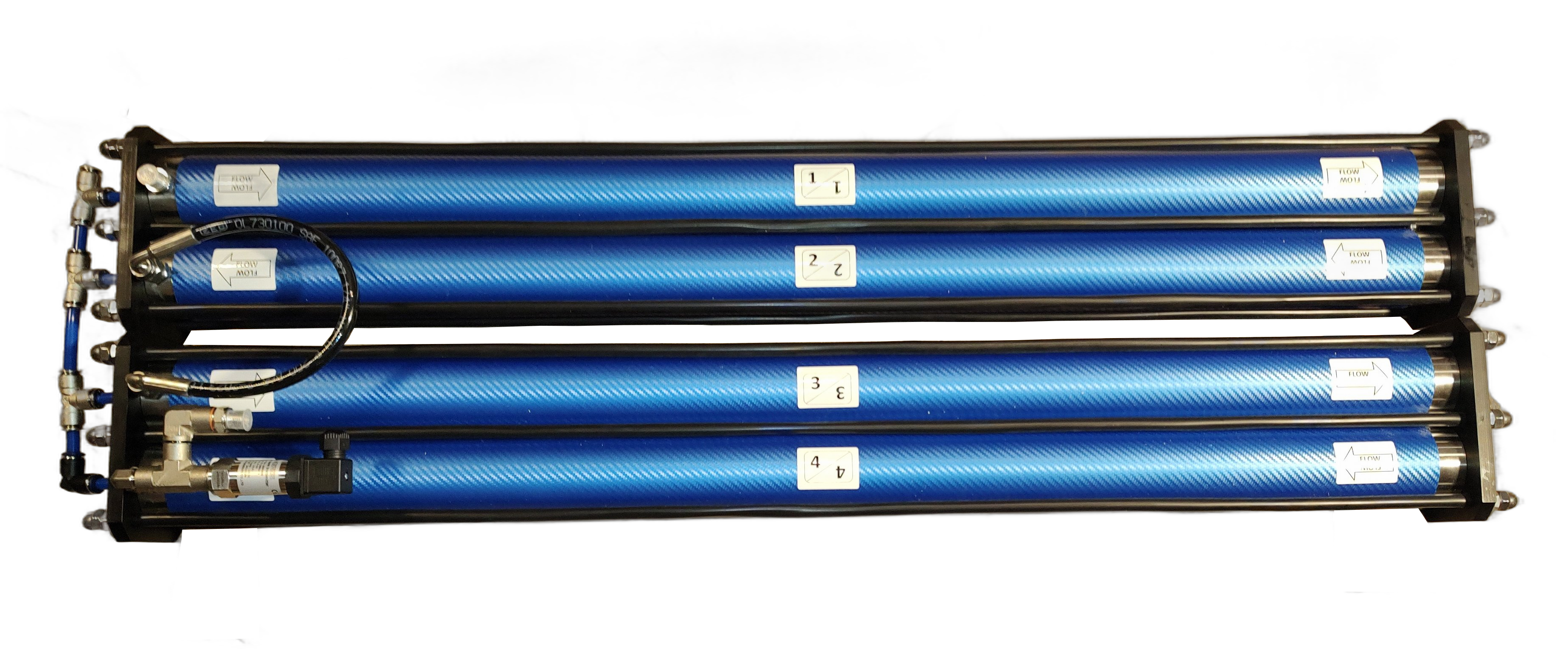
Vessel Blue Gold Watermakers double 4 - INSTALLATION, OPERATION & MAINTENANCE MANUALS

1 – Vessel
2 – First and last heads (threaded)
3 – Intermediate heads (without thread)
4 – Bars
5 – Plates
6 – Washers and Nuts
7 – Brackets
8 – High Pressure Nipples (1/4″NPT x 1/4″ BSPP)
9 – Permeate quick fittings
10 – Nipple between the vessels
11 – Internal O-ring
12 – External O-ring
13 – Permeate hose

The components 7,8,9,13 are not included when the vessels are ordered as spare parts.


Preparation of the membrane vessel head

First and last head of the system
1 – Screw the high-pressure fitting into the stainless steel head.
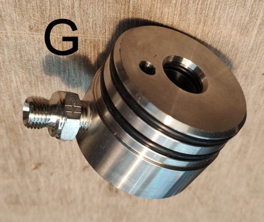
2 – Mount the two O-rings on the membrane vessel heads.
3 – Mount the O-ring on the internal side of the vessel head

Important: the threads of the vessel head and of the nipple are NPT (conical), so in theory there is no need to use a sealant. Please use in any case one turn of Teflon tape or (better) liquid thread sealant.
The thread at the other side of the nipple is BSPP (cylindrical), and cannot get screwed into the vessel head.

Intermediate heads of the system
These heads are different and do not have any thread, because (later) they will connect the vessels over a special nipple with O-rings (n.10 in the above image).

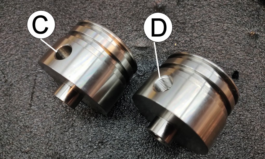
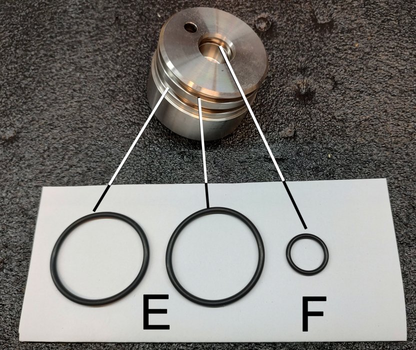
1 – Mount the two O-rings (E) on the membrane vessel heads (C and D).
2 – Mount the O-ring (F) on the internal side of the vessel head (C and D).

Vessel Blue Gold Watermakers Niples - INSTALLATION, OPERATION & MAINTENANCE MANUALS Vessel Blue Gold Watermakers Heads - INSTALLATION, OPERATION & MAINTENANCE MANUALS
Vessel Blue Gold Watermakers OR - INSTALLATION, OPERATION & MAINTENANCE MANUALS Vessel Blue Gold Watermakers head 2 - INSTALLATION, OPERATION & MAINTENANCE MANUALS

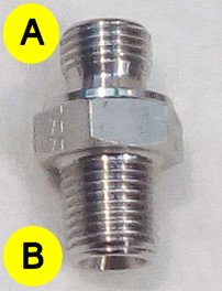
A – 1/4″ BSPP Thread
B – 1/4″ NPT Thread
C – Intermediate Heads without thread
D – First and last heads with 1/4″NPT thread
E – External O-ring
F – Internal O-ring
G – The head is ready


Preparation of the Vessel Pipe

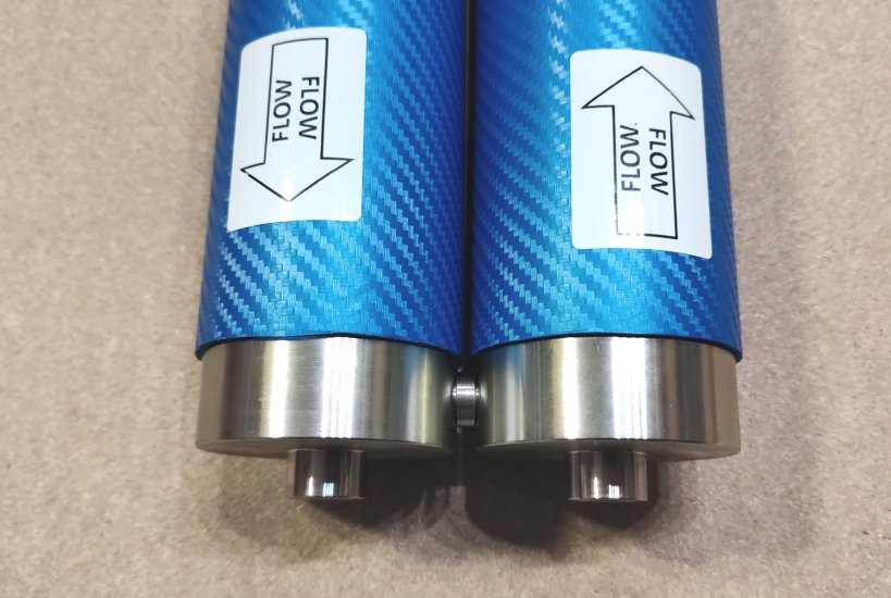
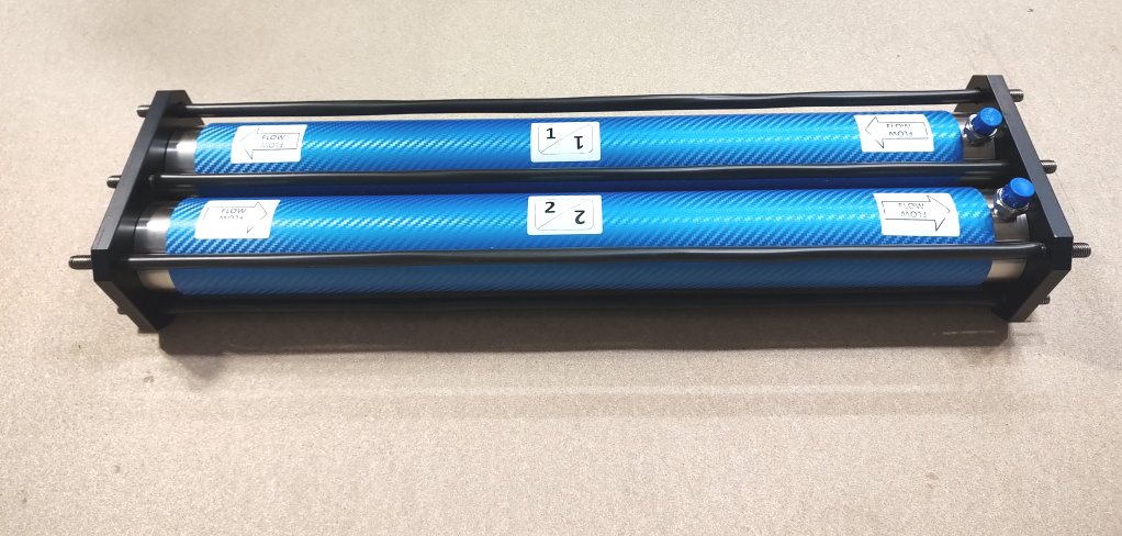
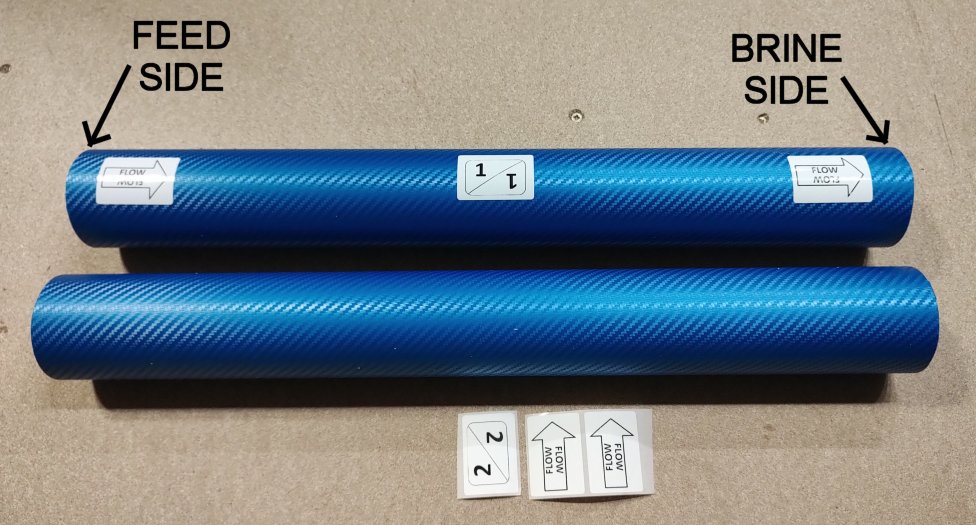
1 – Attach the stickers with the number of the vessel and the flow direction
2 – Keep in mind the difference between FEED SIDE and BRINE SIDE of the vessel!

Vessel Blue Gold Watermakers vessel1 - INSTALLATION, OPERATION & MAINTENANCE MANUALS


Insert the Membrane into the Vessel

  1. First of all you must mount the head to the BRINE SIDE of the vessel.
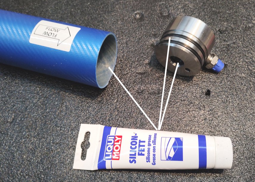
  2. Lubricate with silicon grease the O-rings of the head (internal and external) of the BRINE SIDE
  3. Lubricate with silicon grease the end of the vessel (BRINE SIDE).
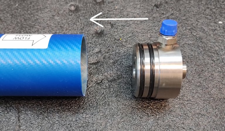
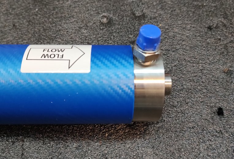
  4. Insert the head into the open end of the vessel (BRINE SIDE).Vessel Blue Gold Watermakers vessel 2 - INSTALLATION, OPERATION & MAINTENANCE MANUALSVessel Blue Gold Watermakers vessel 3 - INSTALLATION, OPERATION & MAINTENANCE MANUALS Vessel Blue Gold Watermakers vessel 4 - INSTALLATION, OPERATION & MAINTENANCE MANUALS
  5. Remove the membrane from its sealed bag.
    Once the membrane is removed from its sealed bag, the watermaker needs to be commissioned within max. 30/60 days.
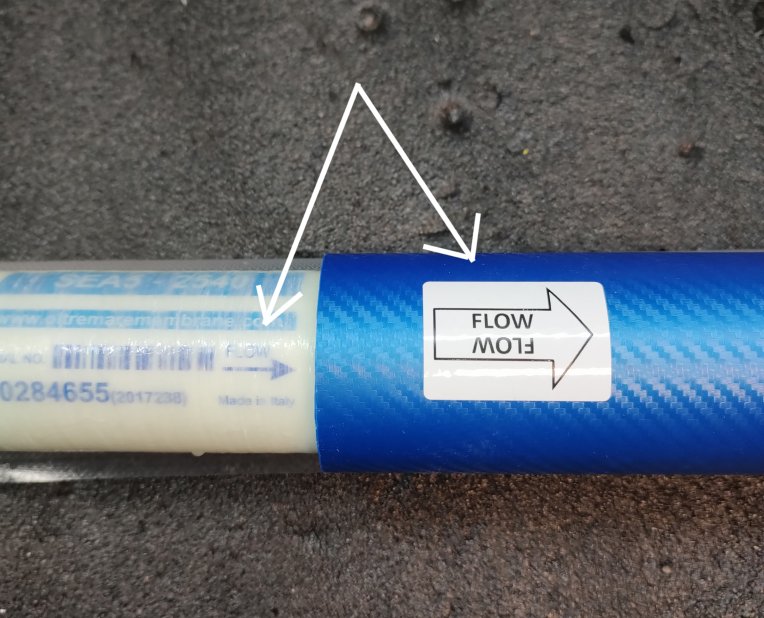
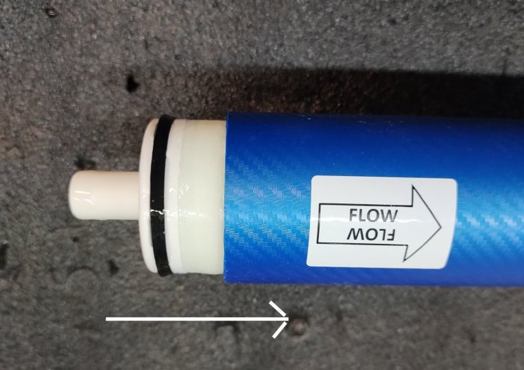
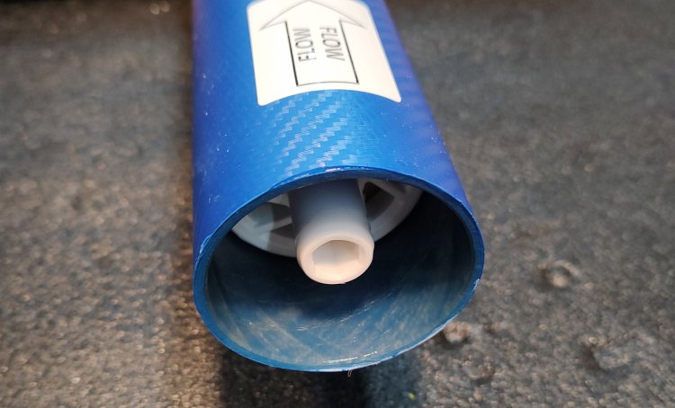
    The membrane, like the vessel, has a FEED SIDE and a BRINE SIDE, and the flow direction is as well printed on its body. The flow direction of the membrane must match with the flow direction of the vessel.
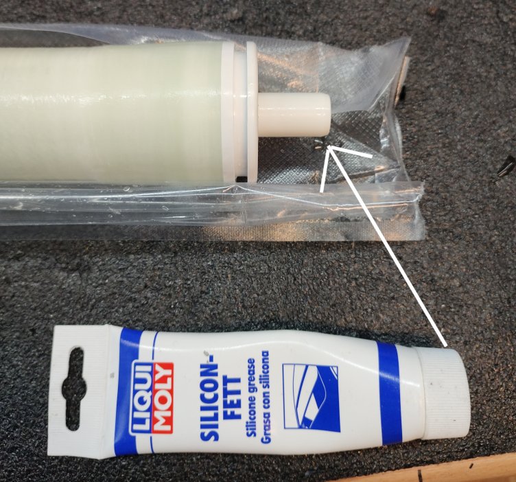
    The membrane has one only O-ring placed at the FEED SIDEVessel Blue Gold Watermakers vessel 5 - INSTALLATION, OPERATION & MAINTENANCE MANUALS
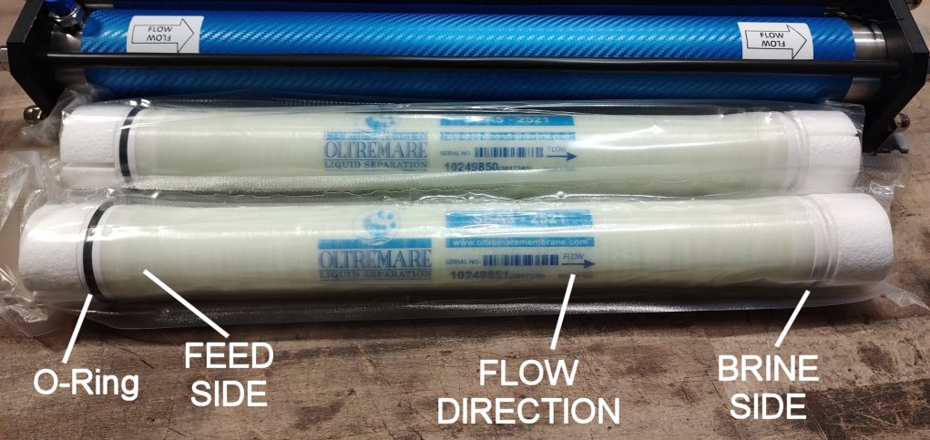
  6. Lubricate the ends of the membrane and the O-ring, and then insert the membrane in the vessel following the flow direction
    Vessel Blue Gold Watermakers vessel 6 - INSTALLATION, OPERATION & MAINTENANCE MANUALS Vessel Blue Gold Watermakers vessel 7 - INSTALLATION, OPERATION & MAINTENANCE MANUALS Vessel Blue Gold Watermakers vessel 8 - INSTALLATION, OPERATION & MAINTENANCE MANUALS Vessel Blue Gold Watermakers vessel 9 - INSTALLATION, OPERATION & MAINTENANCE MANUALS Vessel Blue Gold Watermakers vessel 10 - INSTALLATION, OPERATION & MAINTENANCE MANUALS
  7. Lubricate with silicon grease the O-rings of the head (internal and external) of the FEED SIDE.
    This head may be with or without thread, depending on the number of the vessels in the system:

    • – In a system with one vessel both the heads are threaded
    • – In a system of two vessels, both the vessels have one head with thread and one head without.
    • – In a system with three or four vessels, the intermediate vessels have both heads not threated, and the first and the last are like in two vessels system
  8. Insert the head into the open end of the vessel (FEED SIDE).
    Vessel Blue Gold Watermakers vessel 11 - INSTALLATION, OPERATION & MAINTENANCE MANUALS Vessel Blue Gold Watermakers vessel 12 e1684082076802 - INSTALLATION, OPERATION & MAINTENANCE MANUALS

Assemble the Vessels in a System of One or More Vessels

We show in the images a system of 2 vessels:

Vessel Blue Gold Watermakers vessel 13 - INSTALLATION, OPERATION & MAINTENANCE MANUALS

  1. Lubricate the O-rings of the special nipple and insert it into the holes of the heads.
    Now the vessels are connected each other
    Vessel Blue Gold Watermakers vessel 14 - INSTALLATION, OPERATION & MAINTENANCE MANUALS Vessel Blue Gold Watermakers vessel 15 - INSTALLATION, OPERATION & MAINTENANCE MANUALS
  2. Insert the heads into the holes of the plates and then insert the bars.
    Vessel Blue Gold Watermakers vessel 16 - INSTALLATION, OPERATION & MAINTENANCE MANUALS Vessel Blue Gold Watermakers vessel 17 - INSTALLATION, OPERATION & MAINTENANCE MANUALS
  3. Place the washers and screw the hex. nuts in both the plates. Tighten the nuts with 2 wrenches 17 mm.
    It is not needed to overtighten the nuts.
  4. Screw the blind nut and fit the inox brackets to the plates as shown in the images.
    Vessel Blue Gold Watermakers vessel 18 - INSTALLATION, OPERATION & MAINTENANCE MANUALS Vessel Blue Gold Watermakers vessel 19 - INSTALLATION, OPERATION & MAINTENANCE MANUALS
  5. Insert and screw the plugs at one side of the outlet of the permeate
    Vessel Blue Gold Watermakers vessel 20 - INSTALLATION, OPERATION & MAINTENANCE MANUALS
  6. Mount the quick fittings at the other side of the outlet of the permeate.
    Vessel Blue Gold Watermakers vessel 21 - INSTALLATION, OPERATION & MAINTENANCE MANUALSVessel Blue Gold Watermakers vessel 22 - INSTALLATION, OPERATION & MAINTENANCE MANUALS
  7. You got the job done!
    The vessel rack can be mounted also vertically. In this case please take care that the outlet of the permeate with the quick fittings, stands on top
    The 2 elements vessel racks coupled with the Clark pump can’t be mounted vertically. If they need to be mounted vertically, please ask our technical office before purchasing, in order to deliver a special version of the coupling between the 2 vessels of the system.

This series of energy recovery water maker is equipped with the best and most advanced Clark pump on the market today:
The Third Generation Enhanced Clark Pump, built by the creators of the original Clark pump in Canada.
This pump adopts completely different techniques and materials from the Spectra and Schenker ones, which now definitely belong to an obsolete technology. Unparalleled reliability for this new system. Take 4 minutes (only 4!) to watch the video below to get a good understanding of the big differences with other pumps on the market.

clark video 1 - INSTALLATION, OPERATION & MAINTENANCE MANUALS

Thank you for choosing the AquaBoost reverse osmosis watermaker, equipped with automatic pressure regulation, an automatic flushing system, and the 3rd generation “Enhanced Clark Pump” energy recovery technology.

Adding a low-energy watermaker to your setup can significantly enhance your cruising experience. With proper use, you’ll no longer need to go out of your way to find expensive or unreliable water sources, nor will you need to haul heavy jerry cans from the dinghy.

The AquaBoost is capable of producing enough water for you and your crew to shower daily and can save you money by allowing you to rinse salt from your boat and equipment, reducing both maintenance and replacement costs.

We are confident you will love your new system and are proud to support it with a leading warranty and exceptional customer service.

There are several mistakes that the installer or operator of the AquaBoost might make that could severely damage the watermaker, significantly reduce its lifespan, or even result in personal injury. Understanding what to avoid is essential for proper installation and operation of the AquaBoost. While these points will be discussed in more detail in the relevant sections of this manual, their importance warrants highlighting them here for special attention.

warning image transparent - INSTALLATION, OPERATION & MAINTENANCE MANUALS
Warning: The AquaBoost marine reverse osmosis watermaker is designed to be used in typical sea water. Using taste to test the quality of the product water only works with a sea water feed. Operating in freshwater without sterilizing the product could result in sickness or death.

warning image transparent - INSTALLATION, OPERATION & MAINTENANCE MANUALS
Notice:
Never allow chlorinated water to come in contact with the RO membranes. Oxidants such as chlorine and/or bleach water will destroy the RO membrane.

warning image transparent - INSTALLATION, OPERATION & MAINTENANCE MANUALS
Notice:
Never run the AquaBoost marine reverse osmosis watermaker in oily water. Oil will permanently ruin the RO membrane.

warning image transparent - INSTALLATION, OPERATION & MAINTENANCE MANUALS
Notice:
Do not install the RO membrane module in an area where the RO membranes can become heat soaked to temperatures above 113°F/45°C.

warning image transparent - INSTALLATION, OPERATION & MAINTENANCE MANUALS
Notice:
The RO membrane module is shipped already mounted, but it contains a storage/preservative solution which must be purged at system start-up.

warning image transparent - INSTALLATION, OPERATION & MAINTENANCE MANUALS
Notice:
A proper cables section and a good electrical supply to the feed pump is mandatory for proper system operation.

warning image transparent - INSTALLATION, OPERATION & MAINTENANCE MANUALS
Notice:
Never use a 5-micron “carbon” filter in place of the supplied 5-micron prefilter element. Use only 5-micron melt blown filters.

warning image transparent - INSTALLATION, OPERATION & MAINTENANCE MANUALS
Notice:
Only use 1% SMBS as storage chemical solution. Other products may damage the system.

Production Rate: 53 liter per hour, 14 Gallons per hour :
The production rate is set by the displacement of the Enhanced Clark Pump energy recovery device and the feed flow rate. The AquaBoost marine reverse osmosis watermaker uses a 15% displacement Clark Pump so 15% of the feed water flow is turned into product water. Water temperature and salinity affect operating pressure but has little effect on production rate. Changes in feed flow does have an effect, the more feed flow the more product. Supplying good voltage to the feed pumps gives the best production rate. Running the system while the batteries are bulk charging gives the highest production rate.

Reverse Osmosis Membranes:
The AquaBoost watermaker is equipped with Reverse Osmosis Membrane(s)
Membrane Type: Polyamide Thin-Film Composite
Membrane Model: Seawater 2521 or Seawater 2540
Range of Operating Pressures: 45 to 69 bar (650 to 1000 psi)
Normal Operating Pressure: Set by feed water conditions and feed flow rate.
Salt Rejection rate: 99.4%
Maximum Operating Temperature: 45°C (113°F)
Minimum Storage/Operating Temp: 0°C (32°F)
Maximum Operating Pressure: 69 bar (1,000 psi)
Maximum Pressure Drop: 1 bar (15 psi)
pH Range, Continuous Operation: 2-11
pH Range, short-term cleaning: 1-12
Free Chlorine Tolerance: <0.1ppm
Electrical Power Requirements:
20.0 amps @ 12.5-14.4 VDC
10.0 amps @ 25.0 – 28.8 VDC

The Enhanced Clark Pump Hydraulic Pressure Intensifier:
Manufactured by ElectroMaax for marine and military use. The Enhanced Clark Pump uses the Feed
pump flow pressure to intensify the pressure of the flow through the RO membranes high enough for
reverse osmosis to occur. There are no electrical components.
Check out this video, it explains the upgrades and benefits of the 3rd generation Enhanced Clark Pump over similar ones like Spectra or Schenker.

clark video 1 - INSTALLATION, OPERATION & MAINTENANCE MANUALS

Displacement: 15 %
Feed Flow range: 3.78 lpm (1.0 gpm) to 15.14 lpm (4.0 gpm)
Maximum Inlet pressure: up to 8.6 bar (125 psi)
Maximum Working Pressure: 68.9 bar (1000 psi)
Maximum operating temperature: 45℃ (113°F)
Maximum storage temperature: 60.0℃ (140℉)
Pump Dimensions: 67cm (26.38”) W, 14.6cm (5.75”) D, 20.32cm (8.0”) H
Pressure Relief Valve: Manually open ½ turn for priming and servicing

Feed Pump:
Motor: Permanent magnet type, fully enclosed, 300 Watt
Pump Body: Nichel Plated Brass
Pump Type PEEK Gears Type
Typical Amp Draw: 19 Amperes @12VDC 10 Amperes @24VDC
Recommended fuse size: 25 amps, 12VDC 15 amps, 24VDC

Pressure Vessel:
Composite material: fiberglass/epoxy compound with PTFE heads. They combine a really great look with an extreme ease of installation, requiring no high-pressure hose to interconnect each other in multi-membrane systems, thanks to the side ports machined in the heads. Easily demountable for membrane replacement.
Compact movable unit made by high performance composite material, very light and strong. This kind of RO pressure vessel is easy to handle and fit aboard. Designed for a continuous long-term use and for a maximum working pressure of 70 bars. Great, clean and elegant design.
Max continuous operating pressure 70 Bar (1000 psi)
Single 2540 Vessel
Double 2521 Vessel

Prefilter and Carbon Filter housings:
Industry standard, 10 inch, plastic, filter housings. Accepting 10” DOE filter cartridges.

Control Panel:

Screenshot 2024 11 24 214721 - INSTALLATION, OPERATION & MAINTENANCE MANUALS
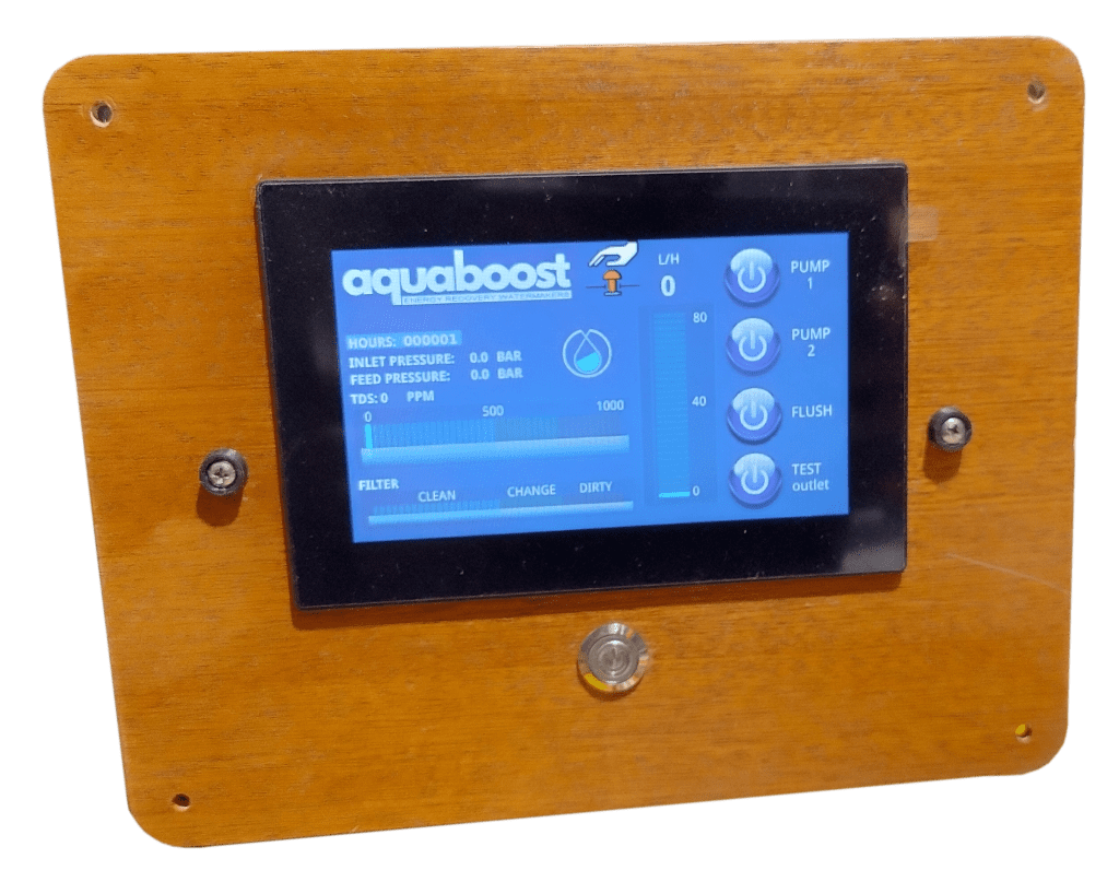
The “Digital” version of this watermaker comes with the “All in One” Control Panel with Touch Screen Display 4.3″.
Dimensions: 7.5” (19 cm) W, 5.9” (15 cm) H, 3.9” (10 cm) depth
The “Analogic” version of this watermaker comes with a very small and simple panel for switching on the feed pump and the flushing solenoid valve. Only one switch is basically needed to run the desalinator, as the working pressure adjusts automatically.
Dimensions: 5.9” (15 cm) W, 5.9” (15 cm) H, 3.9” (10 cm) depth

Clark Pump and Pressure Vessel Assembly, 2-21” or 1-40” Membranes:
Dimensions: 16.3” (41.3 cm) W, 24.7” (62.8 cm) L, 8.4” (21.3 cm) H
1-40” membrane 43.5” (1106 mm) L
2-21” membrane 24.7” (628 mm) L
Weight: 2-21” 40.0 lbs. (18.2 kg), 1-40” 33.6 (15.2 kg)

The AquaBoost marine reverse osmosis watermaker can be purchased with 2 different membrane configurations. All configurations are sent with the Clark Pump and the Membrane(s) mounted together on an aluminium base frame and plumbed together with high pressure hoses. If a frame assembly cannot be reasonably mounted as a unit, the Clark pump and membrane(s) can be separated for custom mounting. Usually, new custom length HP hoses are need to be ordered separately.

The membranes must always be mounted horizontally. If they are to be mounted vertically it is necessary to consult with our office!!

Configuration 2 membranes and feed pump - INSTALLATION, OPERATION & MAINTENANCE MANUALS

1. Double 21” membranes in series. One is mounted on top of the other to conserve space. Ideal for where a 40” membrane would be hard to fit.

Configuration 1 membrane and feed pump - INSTALLATION, OPERATION & MAINTENANCE MANUALS
2. One 40” Membrane is the simplest, lightest and the most energy efficient configuration. Shipping is more expensive and installation more challenging.

The AquaBoost marine reverse osmosis watermaker is simple to install. When all the components are connected in the right order the system will perform as designed and give all the freshwater you need for a long time. Every install is going to be different in where and how the components are mounted so forethought is necessary for the ideal layout for your installation. If you are already familiar with watermakers without an energy recovery device like the Clark Pump, please try to forget what you know as much won’t apply to this system and may lead you astray. Please read the instructions and don’t make assumptions based on older types of systems.

Mounting the Components without service valves - INSTALLATION, OPERATION & MAINTENANCE MANUALS

Simplified Component and Plumbing Layout to familiarize yourself with how the major components interconnect.

Before starting the installation process, please read the entire installation guide carefully. Take a moment to review the following installation notes to ensure your AquaBoost marine reverse osmosis watermaker performs optimally, lasts longer, and is easy to operate and maintain.

Every boat is unique, so if you have any questions or uncertainties, don’t hesitate to contact us. We’re here to assist you and would rather help you address any concerns now than after the system is installed, with components mounted and holes drilled into your boat.

Installation Notes:

A. When choosing a mounting location, ensure easy access to components requiring regular maintenance, such as the pressure relief valve on the Clark pump, pre-filters, membrane, flush filter, and service valves.

B. The boost/feed pump needs a 25-amp fuse or breaker for 12 VDC systems, or a 15-amp fuse for 24 VDC systems.

C. Route both high-pressure and low-pressure water lines carefully to avoid chafing or tight bends that could cause kinks and restrict water flow.

D. Use Teflon tape or Loctite 55 sealing cord for water line fittings, avoiding the first thread. Do not use paste-type sealants, as they can enter the system and damage the membrane or Clark Pump.

E. Install the RO membrane in a location where it won’t be exposed to temperatures above 45°C (113°F) when not in use.

F. Good planning and component layout are crucial for a successful installation. Dry-fit the components first to confirm the plumbing layout before securing them in place.

G. Avoid sharp 90-degree fitting turns. A longer tube with smooth bends is more efficient than a shorter tube with hard 90-degree angles, as it reduces flow resistance.

H. Electrical connections should be handled by someone knowledgeable and experienced with 12 and 24 VDC systems.

I. Voltage drop can reduce system performance. Use the recommended wire sizes (or bigger) to ensure proper operation.

Seacock
INTAKE SEACOCK:
Install a dedicated ¾” seacock with a forward-facing scoop, positioned as low and centrally on the boat as possible. Avoid placing it near or downstream from a head outlet or sink drain. It is recommended to have this installation completed by a professional yard during a haul-out. While sharing a through-hull with another system is not ideal, it may be acceptable in specific circumstances. Use 20 mm (not less) hose barbs made from the same material as the valve, along with a reinforced hose rated for below-waterline use, connecting it to the sea strainer. Please note that the seacock and hose are not included in the Aquaboost kit.

strainer
SEA STRAINER

The Sea Strainer protects the check valves in the feed pump by preventing debris from jamming them. It is installed between the intake thru-hull valve and the feed pump. The ideal location is just above the waterline, though it can also be placed above or below it. To avoid spills during servicing, do not mount the strainer over sensitive equipment.

Use 20 mm (not less), reinforced hose between the intake thru-hull and the Sea Strainer, and double clamp all hose connections. Ensure there is sufficient clearance below the bowl for easy removal. Once you’ve chosen a location, secure the mounting bracket with screws. Check the housing for a directional arrow to confirm the flow direction, then attach the hose and tube fittings through the bracket and into the strainer body. These fittings will secure the strainer body in the bracket.
During servicing, take care not to misplace the bowl gasket. After servicing, ensure the strainer bowl is screwed on tightly to prevent air from entering the system. Please note that the sea strainer is not included in the Aquaboost kit.

carbon filter
CARBON FILTER FOR FLUSHING WATER
The Flushing function is used to flush the seawater out of the system after use. A carbon filter is installed to remove any chlorine from the ship’s water tank, as chlorine can damage the membrane. Mount the filter vertically using the built-in mounting bracket, ensuring at least 5 cm of clearance below the assembly to allow easy access for opening the filter housing.
Note that fresh water will spill during filter replacement.

The inlet of the filter is connected to the ship’s pressurized water system using owner-supplied hose or tubing and a Tee-fitting that matches the ship’s plumbing. The outlet from the flush filter is connected to a Tee installed in the feed line before the feed pump. Replace the carbon filter every 6 months of use or whenever the system comes out of long-term storage.

amita - INSTALLATION, OPERATION & MAINTENANCE MANUALS
CHECK VALVES

The Flush Check Valve prevents pressurized, filtered flush water from flowing back out through the intake thru-hull and ensures it is directed to the Feed Pump. For optimal performance, the valve should be installed as close as possible to the Flush Tee to avoid any saltwater sitting between the valve and the Tee.

feed pump

FEED PUMP
The Feed Pump Assembly is a PEEK gears type automatic pressure pump . These pumps are similar to the marine ones but their delivery and pressure are specifically designed for this application. There is no need to adjust the pressure, and these pumps are self-priming (max. -1,5 meters). Have enough space around it to dissipate the heat and only if needed, place vents below and above the pumps to allow for convection currents to take away the heat.

Filter and Sensors
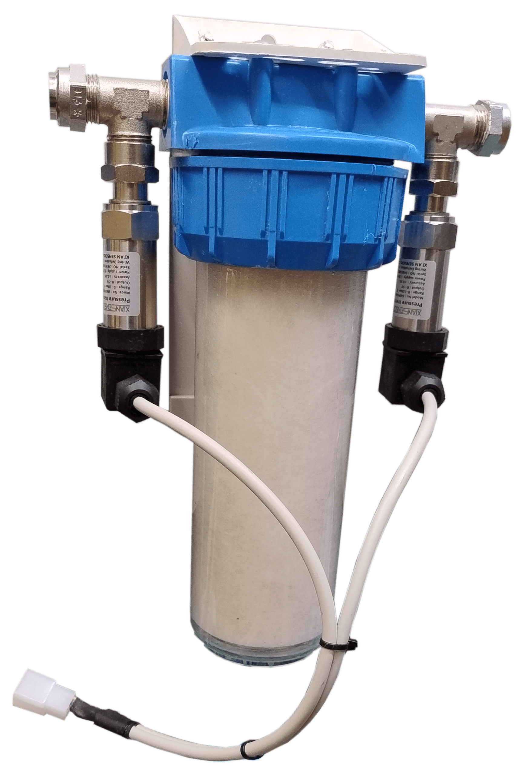
PREFILTER WITH PRESSURE SENSORS

In the DIGITAL version of the machine, the 5-micron prefilter is delivered with two pressure sensors which measure the pressure difference between inlet and outlet and determine the health of the filter itself.
In the ANALOGIC version an additional gauge is mounted on the inlet of the filter. The user must take care that the reading of the gauge on the Clark pump is not considerably lower than the reading of the gauge on the filter.
Use only melt blown and not wire wounded cartridges!

Gauge
ACCUMULATOR TANK WITH PRESSURE GAUGE

The Accumulator Tank must be pressurized to 4 bar (60 psi) before use. It is used to smooth out the feed flow to the Clark Pump when it “shifts” and reverses direction internally. It absorbs pressure spikes during a shift which can affect the pressure switch on the Feed Pump. Use a bicycle pump to fill to a higher pressure, and then use an accurate tire pressure gauge to set it to 60 psi. If the Clark Pump shifts are affecting the Feed Pump, check the pressure while the system is off, and the Pressure Relief Valve on the Clark Pump is open. The accumulator tank and the pressure gauge are provided already mounted on the inlet of the Clark Pump.

Clark Pump - INSTALLATION, OPERATION & MAINTENANCE MANUALS

3rd GENERATION ENHANCED CLARK PUMP
The Clark pump and the vessels with the membranes are mounted on an aluminum frame and only need to be connected to:
– Prefilter (use 20mm diameter pipe, no smaller)
– Overboard discharge (concentrated, use 20mm diameter pipe)
– Permeate pipe to freshwater tank (provided in kit).
No electrical connection is needed.
If the membranes need to be separated for space reasons and mounted vertically, consult with us BEFORE purchasing the watermaker.

The Clark Pump has two brine discharge ports to choose from. Both are plugged at the factory for shipping. Remove the plug from the one that best suits the plumbing arrangement and leave the other side plugged. The Pressure Relief Valve is all plastic and is only finger tightened. Do not over tighten. Leave the Pressure Relief Valve open ½ turn for the initial commissioning.

Membranes assembly
PRESSURE VESSEL AND RO MEMBRANE ASSEMBLY

The pressure vessels come with the membranes already inserted and are ready for commissioning for the first time. It is recommended that the machine be commissioned within a maximum of one month after delivery.
The pressure vessels assembly and the Clark pump are mounted on an alu frame for an easy installation aboard. Our reverse osmosis RO pressure vessels in composite are the best product in this segment. They combine a really great look with an extreme ease of installation, requiring no high-pressure hose to interconnect each other in multi-membrane systems, thanks to the side ports machined in the heads.

Aquaboost panel
CONTROL PANEL (DIGITAL and ANALOGIC VERSION)

With the ANALOGIC VERSION of the watermaker is supplied a simple panel including a switch and a solid state relay to drive the feed pump and a switch to perform the flushing. Nothing else is basically needed to drive this watermaker. The regulation of the pressure is automatic.
With the DIGITAL VERSION of the watermaker is supplied our “ALL IN ONE” touch screen display. Please refer to dedicated tab to read how it works.

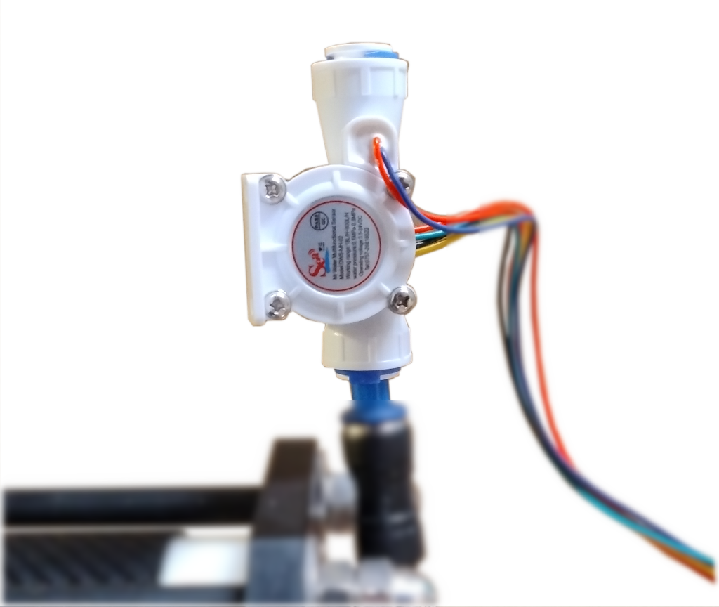
TDS
TDS and FLOW SENSOR

The TDS and FLOW SENSOR is included with the digital version of the water maker. It should be mounted vertically on the permeate outlet so that the water flow goes from the bottom to the top.

easy flushing

EASY FLUSHING SYSTEM
It is mounted on the activated carbon filter and allows flushing of the system at the end of the fresh water production cycle. In the digital version it is connected to the touch screen control panel, while in the analog version it is connected to a simple switch that opens the solenoid valve.

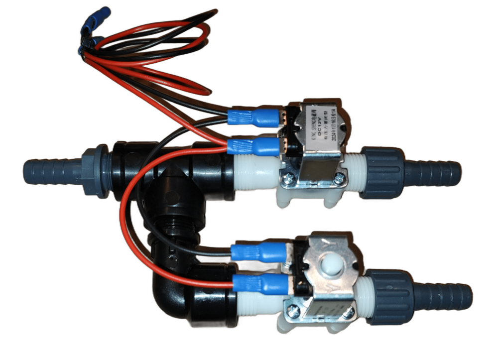
tank-test switch

TANK/TEST SWITCH
This is a system of two solenoid valves (NC and NO) that directs the permeate flow to the tank or to a test outlet (such as a spout in the kitchen sink). It is present only in the digital version, while in the analog version it can be replaced by a customer-supplied three-way ball valve (T-operating).

3-WAYS SERVICE VALVES
These two 3-way ball valves (L-operating) are used to carry out long term storage of membranes or their cleaning with chemical preparations. They are not supplied with the water maker, but the customer can decide to mount them himself. In any case, we recommend using our valves kit for cleaning/preserving/pickling the membranes instead.

DISCHARGE THROUGH HULL
The Owner must provide and install a 1/2” or 3/4″ hull fitting just above the waterline. It is possible to tee it into an existing drain above the waterline but there is a good chance it will cause gurgling noise and flood the boat if the drain through hull valve gets closed. For those reasons, it is highly recommended to install a dedicated through hull for the watermaker

A.
First, refer to the component size tab to identify the spaces on board, where to install the water maker.
B.
Follow the flow diagram and the mounting notes in the component descriptions. Note how the 3-way valves are plumbed, they will always introduce a 90° turn in the flow.
C.
When mounting the components, check the thickness of the bulkhead and cabinet panels and size the fasteners appropriately. If using through bolts, use Nylock nuts and washers. Use fasteners that match the mounting holes in the components or one size under at most.
D.
The length of the feed and discharge tubes do not affect the performance, but many right-angle turns will. Long sweeping turns are better.
E.
Place the Clark Pump/Pressure Vessel assembly for easy access to the pressure relief valve while operating the system and with consideration for how to replace the membrane which means either there is enough room off one end of the Pressure Vessel to remove the membrane in place or the Pressure Vessels needs to be removed to allow access. Allow wrench access to the High-Pressure fittings at the ends of the membrane for removal. The HP fittings require 2 wrenches for assembly or removal. The flexible HP hoses and the swivel fittings in the Clark Pump allow for installation options for fitting access.
F.
The 3-way Service Valves (if mounted by the customer) should be located in the same area where a Service Pail can be securely placed, and the Service Tubes can all reach it at the same time. This is important for ease of use and maintenance. The Service Tubes can be removed or tucked away when not in use.
G.
Place the panel in an area that has easy access.
H.
The Product water must be dropped into the top of the tank without any back pressure. Do not connect it at the bottom outlet of the tank as the head pressure may try to push product water backwards through the membrane. Tee into the tank vent line or add a port into the top of the tank.
I.
Make sure the tank vent is not clogged. If the tank is overfilled, the product will flow harmlessly out the vent.
J.
The Feed Pump Assembly should be mounted to a rigid horizontal surface in a dry area below the waterline or up to 1 meter above the waterline. Best is at or below the waterline. It can also be mounted vertically, in which case place the pump body under the motor

Mounting the Components without service valves - INSTALLATION, OPERATION & MAINTENANCE MANUALS

Components mounted without the 3 ways service valves (the system uses our valves kit for cleaning/preserving/pickling the membranes).
We suggest this kind of installation.


Mounting the Components with service valves

Components mounted with the 3 ways service valves (the system does not use our valves kit for cleaning/preserving/pickling the membranes).

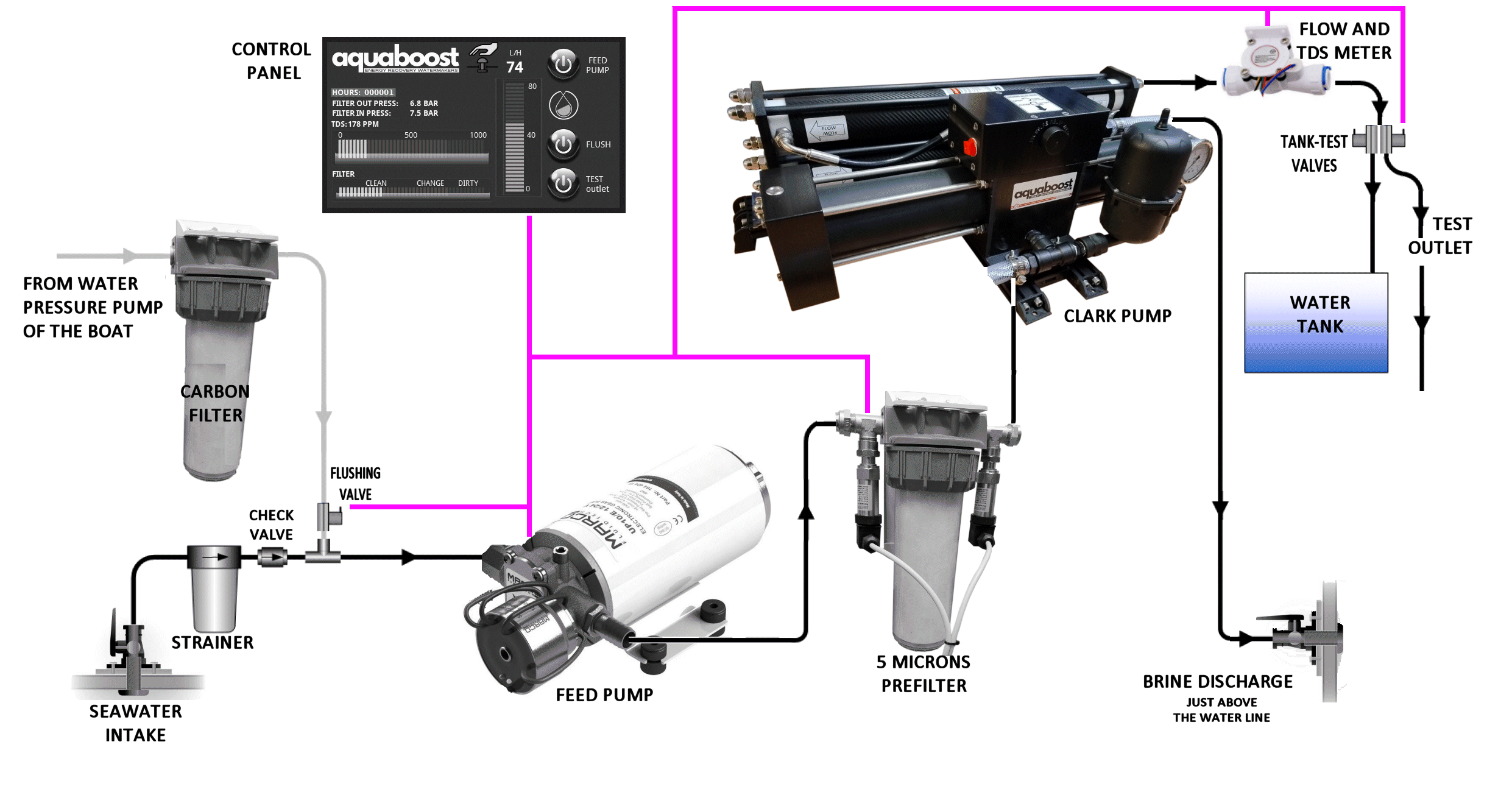
Proper wiring is important to minimize voltage drop between the batteries and the Feed Pumps. Use Marine grade tinned multi strand wire. Pick one of the methods above, taking power from a breaker on the panel or wire an inline breaker directly from the house batteries, whichever is closer. Use cables of 4 mm2 cross-sectional area (or larger). Try to keep connections as short as possible. Using cables that are too thin or too long with inadequate diameter has a negative impact on pump performance. The panel connectors are marked and it is not possible to connect them incorrectly

Mounting the ComponentsElectric connection - INSTALLATION, OPERATION & MAINTENANCE MANUALS

The Commissioning Procedure should be performed at a new system start up. The main function is to prime the Feed Pump, look for leaks, and purge the system of the chemicals used for the storage of the membranes.

DIGITAL VERSION

  1. Open the watermaker intake and discharge through hull valves.
  2. Open the Pressure Relief Valve 1/2 turn from a finger tight closed position.
  3. Remove the inlet pipe of the Clark Pump and send it to a bucket or sink.
  4. Turn on the touch screen panel. Go to the main screen and then to the flushing screen
  5. Select the 4 minutes time and then start the flushing. In this way you purge the air from the carbon filter and part of the circuit.
  6. Look for leaks in the system. If any leaks are found, turn off the system and repair it before continuing. You will need to see water coming out from the hose.
  7. If needed repeat the procedure. This one-time step clears any debris between the Prefilter and Clark Pump.
  8. Reassemble the inlet pipe to the Clark Pump
  9. Switch the touch screen panel off and on again. Go to the main screen, set the Tank/Test switch to TEST and switch the pump on.
    Look for water flowing through the Inlet Strainer. When the feed water reaches the Feed Pump, its sound will change and be uneven then smooth out as the air is purged. Pressure will start to build in the feed pressure gauge and the Clark Pump will make its first “shift” at it starts to circulate water through the membrane. The shifts should start to even out as the air is purged. They may be hard to hear, watch for a rise and fall of boost pressure as the Clark Pump shifts.
  10. With the Feed Pump running, make a visual inspection to ensure that the connections are all leak free. If any leaks are found, turn off the system and repair it before continuing.
  11. Continue to run the system unpressurized (Pressure Relief Valve open) for 15/20 minutes to purge the storage solution from the membrane elements. The Feed pump should be running smoothly now. If not, there is an air leak in the Strainer or Flush systems. Fix before continuing.
  12. After 15/20 minutes and the system is running smooth with regular shifts in the Clark Pump, close the Pressure Relief Valve. The sound of the Feed Pump and the Enhanced Clark Pump shifts will change as high pressure is generated in the Membrane and within a short time  the product water will start to flow through the Flow Meter and then out from the Test outlet.
  13. Check for leaks at the high-pressure hose connections and around the Clark Pump, Membrane end fittings and Control Panel. Recheck the Feed system for leaks. If leaks are found, stop the unit, and correct as needed.
  14. Run the system with the Product Water diverted for 10 minutes to purge the Product Water side of the Membrane to clear any remaining Storage Chemical.
  15. If the TDS meter shows a value below 500 ppm, switch the Tank/Test to the TANK position to fill the tank if desired.

ANALOGIC VERSION

  1. Open the watermaker intake and discharge through hull valves.
  2. Open the Pressure Relief Valve 1/2 turn from a finger tight closed position.
  3. Remove the inlet pipe of the Clark Pump and send it to a bucket or sink.
  4. Turn the flushing switch ON
  5. The flushing is started. Let it run for 3/4 minutes. In this way you purge the air from the carbon filter and part of the circuit.
  6. Look for leaks in the system. If any leaks are found, turn off the switch and repair it before continuing. You will need to see water coming out from the hose.
  7. If needed repeat the procedure. This one-time step clears any debris between the Prefilter and Clark Pump.
  8. Reassemble the inlet pipe to the Clark Pump
  9. Take care that the permeate goes to the test outlet and not to the tank and then turn the switch of the pump ON.
    Look for water flowing through the Inlet Strainer. When the feed water reaches the Feed Pump, its sound will change and be uneven then smooth out as the air is purged. Pressure will start to build in the feed pressure gauge and the Clark Pump will make its first “shift” at it starts to circulate water through the membrane. The shifts should start to even out as the air is purged. They may be hard to hear, watch for a rise and fall of boost pressure as the Clark Pump shifts.
  10. With the Feed Pump running, make a visual inspection to ensure that the connections are all leak free. If any leaks are found, turn off the system and repair it before continuing.
  11. Continue to run the system unpressurized (Pressure Relief Valve open) for 15/20 minutes to purge the storage solution from the membrane elements. The Feed pump should be running smoothly now. If not, there is an air leak in the Strainer or Flush systems. Fix before continuing.
  12. After 15/20 minutes and the system is running smooth with regular shifts in the Clark Pump, close the Pressure Relief Valve. The sound of the Feed Pump and the Enhanced Clark Pump shifts will change as high pressure is generated in the Membrane and within a short time  the product water will start to flow through the flow indicator and then out from the Test outlet.
  13. Check for leaks at the high-pressure hose connections and around the Clark Pump, Membrane end fittings and Control Panel. Recheck the Feed system for leaks. If leaks are found, stop the unit, and correct as needed.
  14. Run the system with the Product Water diverted for 10 minutes to purge the Product Water side of the Membrane to clear any remaining Storage Chemical.
  15. Check the water quality with your hand held TDS meter and if the TDS meter shows a value below 500 ppm, switch the permeate flow to fill the tank if desired.

DIGITAL VERSION

  1. Open the watermaker intake and discharge through hull valves.
  2. Open the Pressure Relief Valve on the Clark Pump 1/2 turn or, if the system has been recently run and is well primed, the Pressure Relief Valve can remain closed.
  3. Switch the touch screen panel ON. Go to the main screen, set the Tank/Test switch to TEST and switch the pump ON.
    Listen for the Feed Pump to run smoothly and the Clark Pump is shifting normally.
  4. Close the Pressure Relief Valve finger tight (if opened). Watch for water flow at the digital Flow Meter.
  5. When the TDS meter shows a value below 500 ppm, switch the Tank/Test to the TANK position to fill the tank if desired.
  6. If the water tank overfills, the water will overflow out the vent but should not cause a problem.

ANALOGIC VERSION

  1. Open the watermaker intake and discharge through hull valves.
  2. Open the Pressure Relief Valve on the Clark Pump 1/2 turn or, if the system has been recently run and is well primed, the Pressure Relief Valve can remain closed.
  3. Take care that the permeate goes to the test outlet and not to the tank and then turn the switch of the pump ON.
    Listen for the Feed Pump to run smoothly and the Clark Pump is shifting normally.
  4. Close the Pressure Relief Valve finger tight (if opened). Watch for water flow through the flow indicator.
  5. Check the water quality with your hand held TDS meter and if the TDS meter shows a value below 500 ppm, switch the permeate flow to fill the tank if desired.
  6. If the water tank overfills, the water will overflow out the vent but should not cause a problem.

NORMAL RUN

  1. Watermakers like to run. The best practice is to run until the tanks are full, shut down with a freshwater flush, then restart when the tanks are down after a few days. Flushing is important because biological growth that can happen inside the membrane in saltwater will not survive in freshwater and vice versa.
  2. Monitor the Filter Status. Filter elements clean better if they are cleaned as soon as they start, or even better, before they start to restrict the flow.
  3. Oil in a membrane will ruin it. It’s usually not a problem as oil normally floats on the surface but if an oil slick is encountered at sea in rough conditions it can get into the system. Avoid running the system.
  4. The system can be run from a brackish or freshwater feed source without having to make any adjustments. A good membrane works equally well in fresh or salt water. The feed pressure will be lower operating in freshwater.

WARNING: The TDS is not 100% reliable when operating with freshwater feed. If the membrane is damaged enough to let a pathogen through it will show up as very high TDS in the product water while operating in salt water but not in freshwater!!

NORMAL SHUT-DOWN, NO FRESHWATER FLUSH:

  1. Turn off the system with the Pump Power buttons on the Panel (Digital or Analogic)
  2. The Pressure Relief Valve can be left closed.
  3. Do not leave the system unflushed for more than a day without running.
  4. A water maker is happiest running for a long time then flushed every time it’s turned off but there are times where it shouldn’t be flushed. Flushing can uses up to 20 liters of freshwater so flushing every time after short runs uses up most or more of the water just made. Being used every day, fouling is minimal so our suggestion is to use the water maker daily and do a flush every 5 days or so.

NORMAL SHUT-DOWN, WITH FLUSH:

  1. Turn off the system with the Pump Power buttons on the Panel (Digital or Analogic)
  2. Make sure the ship’s Freshwater Pressure System is on, with plenty of water in the tank.
  3. With the ANALOGIC version, simply turn the flush switch on. With the DIGITAL version, switch to the flushing screen, select the time and push the start button.
  4. Watch for the Feed Pressure to drop and stabilize at a lower pressure as the salt water is flushed from the membrane. If the Feed Pressure remains steady, the flush is not working. Check if the freshwater pressure is functioning, Flush Valve wire connections are good, and the carbon filter isn’t clogged.
  5. Flushing can be done either with the pressure relief valve closed or open.
  6. A trick for determining the flushing time:
    Disconnect the reject hose from the clark pump and send the flushing water into a bucket. Taste the water coming out at intervals, when it is no longer salty it means the system has been properly flushed and there is no more salt water in it. Make a note of the elapsed time and in the future flush the system for this time without the need to disconnect the reject hose anymore.
  7. With the ANALOGIC version, turn off the flushing switch after the desired time. With the DIGITAL version the system switches off after the preset time. If needed repeat the operation.

Membrane Storage Procedure

The composite polyamide type of the membrane elements must NEVER be exposed to chlorinated water. Any such exposure will cause irreparable damage to the membranes. Absolute care must be taken following the preparation of cleaning or storage solutions to ensure that no trace of chlorine is present in the water. Use ever distilled water or permeate water to carry out the operation.
The storage procedure is divided in three chapters, based on the duration of the storage:

  • Short-term storage of the membrane elements in place in the vessels.
  • Long-term storage of the membrane elements in place in the vessels.
  • Dry storage of the membrane elements as spares or before assembling a watermaker.

Short-Term Storage (Maximum 30 days)

Short-term storage is for periods where the watermaker must remain out of operation for more than five days, but fewer than thirty days, with the membranes in place.

  1. Flush the watermaker with de-chlorinated water, following the procedure described in the tab above.
  2. Reflush as described above at 5-day intervals.

Long-Term Storage (Maximum 6 months)

Long-term storage is for periods where the watermaker must remain out of operation for more than 30 days with the membranes in place.

  1. Flush the watermaker with permeate water or in any case with de-chlorinated water
  2. Mount our valves kit for cleaning/preserving/pickling the membranes:
  3. Remove the high pressure hoses from the inlet and the outlet of the membrane rack. ALWAYS USE TWO WRENCHES TO CARRY OUT THE OPERATION!
  4. Mount the two valves as shown in the images and tighten them using two wrenches.
  5. Connect the hose to an automatic cheap pressure pump and to a 10 liters canister where you will prepare the preservative solution. You have created a closed loop.
  6. Prepare 10 liters of solution following the instructions of the producer. Keep in mind that:
    Every 2540 membrane contains 1.5 liters of water and every 2521 membrane contains about 1 liter of water.
  7. Wire the pump to a 12 Volt source, open the valve at the outlet of the membrane rack and then open the valve at the inlet. The pump will start.
  8. Recirculate the solution for a few minutes.
  9. Close the valve at the outlet of the membrane rack and soon after the valve at the inlet.
  10. The vessels are now filled with preservative solution and no bubble of air should be inside. Check for drops/leaks. Flush the cheap pressure pump with some freshwater.
  11. When the watermaker is ready to be returned in service, remove the valves, clean them, reconnect the high pressure hoses, flush the plant and then start it. Discard the water produced in the first 30 minutes.
    With this system the solution does not flow through the other components of the watermaker and the two valves ensure that the system does not empty or air enters.

pickling drawing

If the customer has decided to install the three-way valves for servicing, he can perform the operation using the feed pump and leaving the pressure relief valve open. He will have to position the valves so that the system drains and sucks the solution from the tank or bucket in which it was prepared.

Storage before installation

When RO elements are stored prior to installation, they should be protected from direct sunlight and stored in a cool, dry place with an ambient temperature range of 5°C to 35°C New Elements are enclosed in a sealed polyethylene bag containing a storage solution, and then packaged in a cardboard box.

Note: we have a quite big turnover of membranes, so they are never old. We recommend to use the new membranes within one year from the purchase, and in any case not to keep them on board as spares. By the time you go to use them they will probably have gone bad. Membranes are standard size and can be found almost anywhere. We ship them worldwide and they are delivered within a few days.

CLEANING WITH CHEMICALS

The procedure described above can also be used to flush membranes with chemicals:
Keep the following in mind:
Follow the product manufacturer’s instructions for preparation and always use dechlorinated water.
Use the products separately, one after the other, making a rinse with clean, dechlorinated water between the two. Never mix the products. Always use personal protective equipment!

It is highly recommended to use our valves kit and prevent chemicals from passing through the Clark pump.

5 MICRON PREFILTER

The Clark Pump and the RO Membrane must only operate on 5 Micron filtered Feed Water.

Use only melt blown type filters and never reuse a filter after it has been removed from the container, even just to “take a look”.

Do not use activated carbon filters in the 5 micron filter housing!!! They can let off carbon “fines” with first use. These fines will ruin the Clark Pump and void the warranty.
Do not use washable filters, as they may be accidentally damaged during washing. If they are damaged, their efficiency will be compromised and the warranty for the pump will be voided. Always use disposable polypropylene melt blown type filters with a filtration efficiency of at least 85%

The Filter Status Gauge will tell you the condition of the filter while operating. It is recommended to change the filter before it gets to the red zone. In the ANALOGIC Version you must take note of the system pressure value with new filter and replace it when this value decreases by 10/20% approximately.

The service life of the filter elements is closely related to the type of inlet water. When you remove the filter, you may notice that the color of the outer part of the cartridge is greyer than the inner part. The filter cartridge should never turn completely grey, it should be replaced before this happens.

Filter to be changed

  1. Loosen union nut of the housing completely using the wrench and remove the bowl downwards.
  2. Empty the bowl in a bucket and remove the used cartridge.
  3. Wash the bowl.
  4. Insert the new cartridge into the bowl.
  5. Grease the O-rings of the bowls with silicone grease. This facilitates the mounting.
  6. Insert the bowl and fasten it with the union nut by tightening it with the wrench.

ACTIVATED CARBON FILTER

During the flushing, the activated carbon filter protects the reverse osmosis membranes from chemical elements, such as chlorine, which would destroy them. Replace this filter at least every 4/6 months.
Follow the same procedure as described above.

This optionally supplied filter must be inserted into the pipe leading to the tank.
Its function is to stabilize the pH of the permeate and make the taste of the water more pleasant in case it is used for human consumption.
Before it is installed, it should be rinsed for half an hour with tap water. Thereafter it should not be replaced. It works even if the level of the dolomite inside drops. A dolomite bag is provided to eventually restore the level.

The use of this filter is especially recommended if only osmosis water is fed into the tanks and they are never filled with marina tap water.

The following applies generally to all desalination plants. In desalinators with a Clark pump, it is not possible to adjust the pressure, which is automatically managed.

Reverse osmosis watermakers are sophisticated systems that demand meticulous upkeep. When product water flow decreases or TDS levels rise, some boaters who are out cruising are quick to blame the membranes. However, as we explain below, there are various plausible explanations for lower (or higher) product flow rates and TDS increasing.

Feed Water Temperature:

You can quickly gauge the feed water temperature by using a basic thermometer (the thermometers in boat instrumentation are often inaccurate)
The feed water temperature has a notable impact on the flow rate of your product water. With reverse osmosis systems being rated based on feed water conditions of 32,000 ppm, 25°C (77°F), and operating at 55 bar (800 psi), it’s crucial to understand the effect of temperature on product water:

As the temperature increases, you can expect a higher TDS and a greater product flow rate. Conversely, a decrease in temperature results in lower TDS and a lower product flow rate. For instance, at 32°C (90°F), you may produce approximately 25% more water, whereas at 10°C (50°F), you could expect a 50% decrease.

In summary:

  • As Temperature Increases you get:
    – Higher TDS
    – Higher product flow rate
  • As Temperature Decreases you get:
    – Lower TDS
    – Lower product flow rate

Feed Water Salinity:

You can measure feed water salinity easily with a refractometer. A refractometer is a simple-to-use device that utilizes light to measure salinity. If you don’t have a refractometer, you can consult this page that reports salt concentrations in all the seas.
You can see that the salinity of the Mediterranean Sea is among the highest globally (about 38000 PPM), while it is much lower in the North Atlantic and Baltic Sea. There is also a significant difference between the east and west coasts of the U.S.

Effect of Feed Water Salinity on Product Water:
The salinity level of feed water has a notable impact on the flow rate of product water. When the salinity is increased, the total dissolved solids (TDS) in the product water also increase, and the flow rate decreases. Conversely, when the salinity is decreased, the TDS in the product water decrease, and the flow rate increases.

If the feed water has a salinity level of 35,000 ppm, you can anticipate a reduction of approximately 10% in the amount of product water. On the other hand, if the salinity level of the feed water is 25,000 ppm, you can expect a boost of approximately 25% in the amount of product water.

In summary:

  • As Salinity Increases you get:
    – Higher TDS
    – Lower product flow rate
  • As Salinity Decreases you get:
    – Lower TDS
    – Higher product flow rate

Influence of Feed Pressure on Output Water:

Membrane test conditions are set at 55 bar, but you can safely work at 60 bar. Don’t forget, however, that going from 55 to 60 bar increases the load on the pump motor by 10 percent, and consequently the current required and the heat that the motor must dissipate also increases.
So if you can work at 55 bar, be happy with that and do not put unnecessary stress on the motor, which is usually located in an engine room or in a confined space where the ambient temperature is already high and ventilation may be poor.

In summary:

  • As Pressure Increases:
    – TDS is reduced
    – Product flow rate is increased
  • As Pressure Decreases:
    – TDS is increased
    – Product flow rate is decreased

CORRECTION FACTOR TABLE

Divide the productivity by the correction value at the given temperature.
Example for a 100 l/h water maker operating at 20 Celsius degrees:
100 : 1.19 = 84
A 100 l/h water maker will produce approx. 84 l/h if the feed water is 20 degrees instead of 25 degrees.

Correction factor

The following applies to all our reverse osmosis pressure vessels. The colour of the pressure vessels coupled with the Clark pump are black instead of blue, and the heads are made in Teflon.

IMG 20240430 144146102 - INSTALLATION, OPERATION & MAINTENANCE MANUALS

The reverse osmosis pressure vessels in composite by CobrAm are the best product in this segment. They combine a really great look with an extreme ease of installation, requiring no high-pressure hose to interconnect each other in multi-membrane systems, thanks to the side ports machined in the heads.

Our pressure vessels can accommodate any standard 2.5”×21” and 2.5”×40” seawater reverse osmosis membranes.
The end plugs are are machined with a CNC milling from a bar of AISI 316L stainless steel for the maximum in corrosion resistance (Teflon in the models with Clark pump).
The tie bars are as well made of stainless steel, covered with a black PVC duct.
The pressure pipe is coated with a special blue protective film (black in the models with Clark pump).
A pair of stainless steel angle brackets are supplied to fasten the vessels to a floor or to a bulkhead.

In our watermakers the vessels come ready-made with the membranes mounted inside, but we also sell the vessels as spare parts, so it is explained here how they are made and how to insert the membranes.


Parts of the Vessel Rack

Vessel Blue Gold Watermakers double 4 - INSTALLATION, OPERATION & MAINTENANCE MANUALS

1 – Vessel
2 – First and last heads (threaded)
3 – Intermediate heads (without thread)
4 – Bars
5 – Plates
6 – Washers and Nuts
7 – Brackets
8 – High Pressure Nipples (1/4″NPT x 1/4″ BSPP)
9 – Permeate quick fittings
10 – Nipple between the vessels
11 – Internal O-ring
12 – External O-ring
13 – Permeate hose

The components 7,8,9,13 are not included when the vessels are ordered as spare parts.


Preparation of the membrane vessel head

First and last head of the system
1 – Screw the high-pressure fitting into the stainless steel head.
2 – Mount the two O-rings on the membrane vessel heads.
3 – Mount the O-ring on the internal side of the vessel head

Important: the threads of the vessel head and of the nipple are NPT (conical), so in theory there is no need to use a sealant. Please use in any case one turn of Teflon tape or (better) liquid thread sealant.
The thread at the other side of the nipple is BSPP (cylindrical), and cannot get screwed into the vessel head.

Intermediate heads of the system
These heads are different and do not have any thread, because (later) they will connect the vessels over a special nipple with O-rings (n.10 in the above image).

1 – Mount the two O-rings (E) on the membrane vessel heads (C and D).
2 – Mount the O-ring (F) on the internal side of the vessel head (C and D).

Vessel Blue Gold Watermakers Niples - INSTALLATION, OPERATION & MAINTENANCE MANUALS Vessel Blue Gold Watermakers Heads - INSTALLATION, OPERATION & MAINTENANCE MANUALS
Vessel Blue Gold Watermakers OR - INSTALLATION, OPERATION & MAINTENANCE MANUALS Vessel Blue Gold Watermakers head 2 - INSTALLATION, OPERATION & MAINTENANCE MANUALS

A – 1/4″ BSPP Thread
B – 1/4″ NPT Thread
C – Intermediate Heads without thread
D – First and last heads with 1/4″NPT thread
E – External O-ring
F – Internal O-ring
G – The head is ready


Preparation of the Vessel Pipe

1 – Attach the stickers with the number of the vessel and the flow direction
2 – Keep in mind the difference between FEED SIDE and BRINE SIDE of the vessel!

Vessel Blue Gold Watermakers vessel1 - INSTALLATION, OPERATION & MAINTENANCE MANUALS


Insert the Membrane into the Vessel

  1. First of all you must mount the head to the BRINE SIDE of the vessel.
  2. Lubricate with silicon grease the O-rings of the head (internal and external) of the BRINE SIDE
  3. Lubricate with silicon grease the end of the vessel (BRINE SIDE).
  4. Insert the head into the open end of the vessel (BRINE SIDE).Vessel Blue Gold Watermakers vessel 2 - INSTALLATION, OPERATION & MAINTENANCE MANUALSVessel Blue Gold Watermakers vessel 3 - INSTALLATION, OPERATION & MAINTENANCE MANUALS Vessel Blue Gold Watermakers vessel 4 - INSTALLATION, OPERATION & MAINTENANCE MANUALS
  5. Remove the membrane from its sealed bag.
    Once the membrane is removed from its sealed bag, the watermaker needs to be commissioned within max. 30/60 days.
    The membrane, like the vessel, has a FEED SIDE and a BRINE SIDE, and the flow direction is as well printed on its body. The flow direction of the membrane must match with the flow direction of the vessel.
    The membrane has one only O-ring placed at the FEED SIDEVessel Blue Gold Watermakers vessel 5 - INSTALLATION, OPERATION & MAINTENANCE MANUALS
  6. Lubricate the ends of the membrane and the O-ring, and then insert the membrane in the vessel following the flow direction
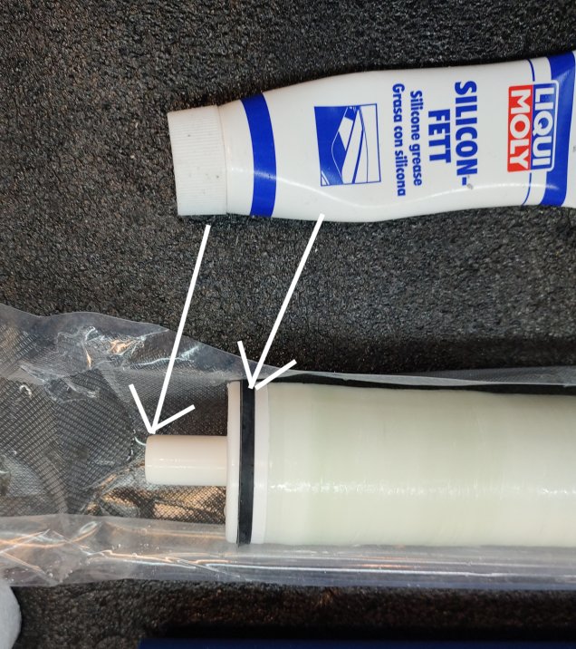
    Vessel Blue Gold Watermakers vessel 6 - INSTALLATION, OPERATION & MAINTENANCE MANUALS Vessel Blue Gold Watermakers vessel 7 - INSTALLATION, OPERATION & MAINTENANCE MANUALS Vessel Blue Gold Watermakers vessel 8 - INSTALLATION, OPERATION & MAINTENANCE MANUALS Vessel Blue Gold Watermakers vessel 9 - INSTALLATION, OPERATION & MAINTENANCE MANUALS Vessel Blue Gold Watermakers vessel 10 - INSTALLATION, OPERATION & MAINTENANCE MANUALS
  7. Lubricate with silicon grease the O-rings of the head (internal and external) of the FEED SIDE.
    This head may be with or without thread, depending on the number of the vessels in the system:

    • – In a system with one vessel both the heads are threaded
    • – In a system of two vessels, both the vessels have one head with thread and one head without.
    • – In a system with three or four vessels, the intermediate vessels have both heads not threated, and the first and the last are like in two vessels system
  8. Insert the head into the open end of the vessel (FEED SIDE).
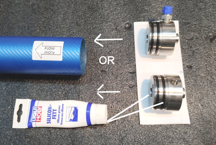
    Vessel Blue Gold Watermakers vessel 11 - INSTALLATION, OPERATION & MAINTENANCE MANUALS Vessel Blue Gold Watermakers vessel 12 e1684082076802 - INSTALLATION, OPERATION & MAINTENANCE MANUALS

Assemble the Vessels in a System of One or More Vessels

We show in the images a system of 2 vessels:

Vessel Blue Gold Watermakers vessel 13 - INSTALLATION, OPERATION & MAINTENANCE MANUALS

  1. Lubricate the O-rings of the special nipple and insert it into the holes of the heads.
    Now the vessels are connected each other
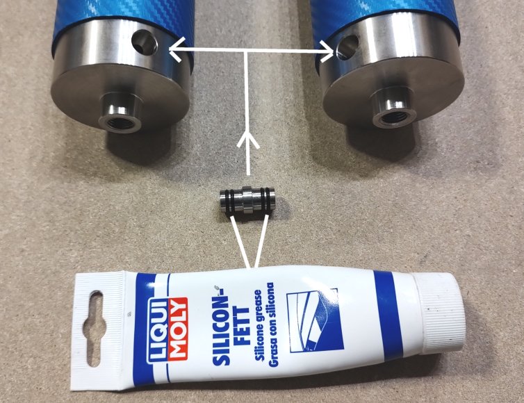
    Vessel Blue Gold Watermakers vessel 14 - INSTALLATION, OPERATION & MAINTENANCE MANUALS Vessel Blue Gold Watermakers vessel 15 - INSTALLATION, OPERATION & MAINTENANCE MANUALS
  2. Insert the heads into the holes of the plates and then insert the bars.
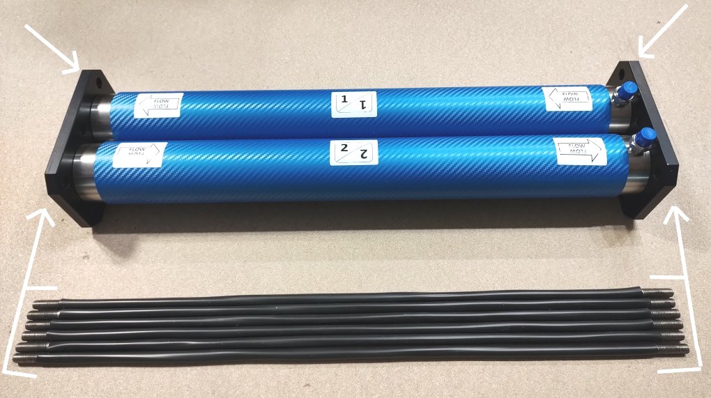
    Vessel Blue Gold Watermakers vessel 16 - INSTALLATION, OPERATION & MAINTENANCE MANUALS Vessel Blue Gold Watermakers vessel 17 - INSTALLATION, OPERATION & MAINTENANCE MANUALS
  3. Place the washers and screw the hex. nuts in both the plates. Tighten the nuts with 2 wrenches 17 mm.
    It is not needed to overtighten the nuts.
  4. Screw the blind nut and fit the inox brackets to the plates as shown in the images.
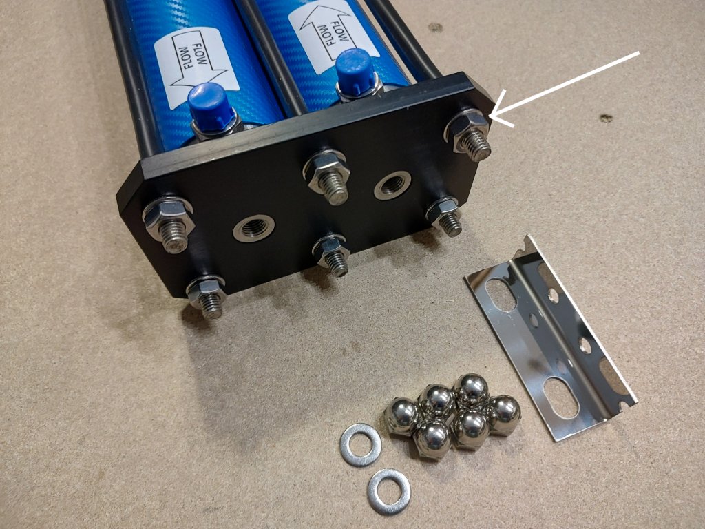
    Vessel Blue Gold Watermakers vessel 18 - INSTALLATION, OPERATION & MAINTENANCE MANUALS Vessel Blue Gold Watermakers vessel 19 - INSTALLATION, OPERATION & MAINTENANCE MANUALS
  5. Insert and screw the plugs at one side of the outlet of the permeate
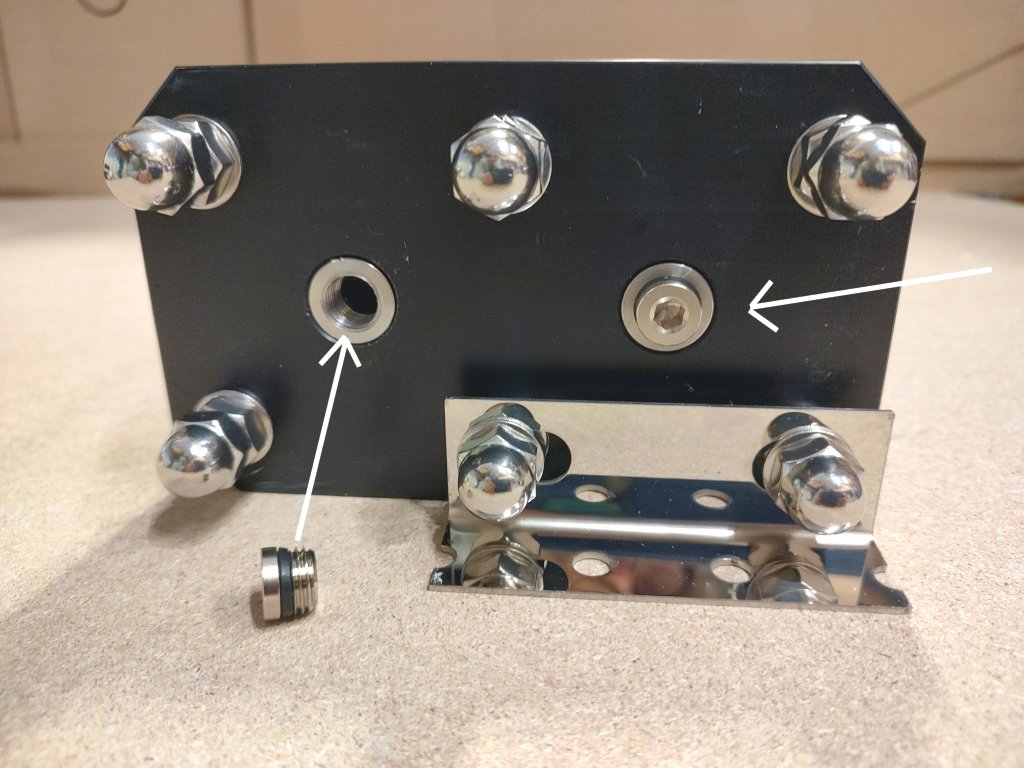
    Vessel Blue Gold Watermakers vessel 20 - INSTALLATION, OPERATION & MAINTENANCE MANUALS
  6. Mount the quick fittings at the other side of the outlet of the permeate.
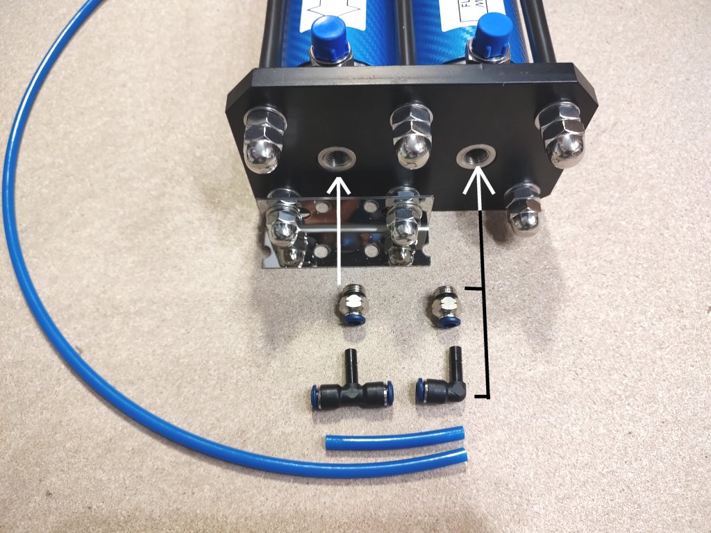
    Vessel Blue Gold Watermakers vessel 21 - INSTALLATION, OPERATION & MAINTENANCE MANUALSVessel Blue Gold Watermakers vessel 22 - INSTALLATION, OPERATION & MAINTENANCE MANUALS
  7. You got the job done!
    The vessel rack can be mounted also vertically. In this case please take care that the outlet of the permeate with the quick fittings, stands on top
    The 2 elements vessel racks coupled with the Clark pump can’t be mounted vertically. If they need to be mounted vertically, please ask our technical office before purchasing, in order to deliver a special version of the coupling between the 2 vessels of the system.

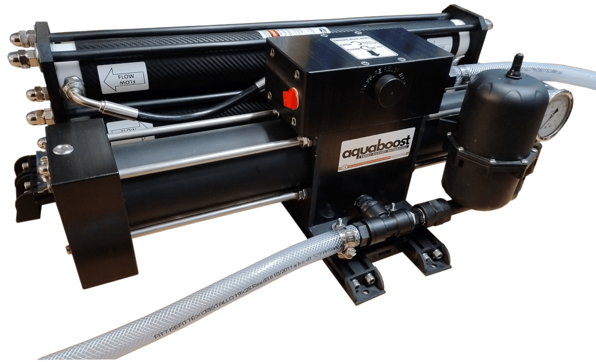
We are working hard to make the manual for this watermaker available online. It will be published by the first week of January 2025.
In the meantime, please refer to the manual shown in the “Just Water” tab.

cover manual 2024 2 - INSTALLATION, OPERATION & MAINTENANCE MANUALS

DOWNLOAD OUR 2024 Watermaker Manual

This Blue Gold watermaker manual covers all our 2024 models in 3 languages: English, German and Italian (French and Spanish desalinator manual is going to be published shortly).

Click to Download!

OLD Blue Gold Watermakers MODELS (Before 2024)

Click the button below to reach the page with the documentation (watermaker manual) of the old of reverse osmosis Blue Gold marine watermakers models.

Old Documents

Watermaker control panel universal model

Watermaker control panel in Mahogany or ABS (carbon look) 3 mm. thickness. It can work with almost any brand of marine watermaker and boat desalinator.

The 4.3” Touch Screen Panel is an advanced device delivered as default in all the Blue Gold Watermakers. With this panel you can visualize all the parameters of the machine and drive all the pumps and valves. The simplest way to run your water maker!

Blue Gold Watermakers Touch Screen Display (Main Screen)

This small panel makes the life simpler. Installation is also much easier, and it fits perfectly into any space on your boat. It is available in mahogany plywood as a default, but it can also be ordered in black with carbon effect.
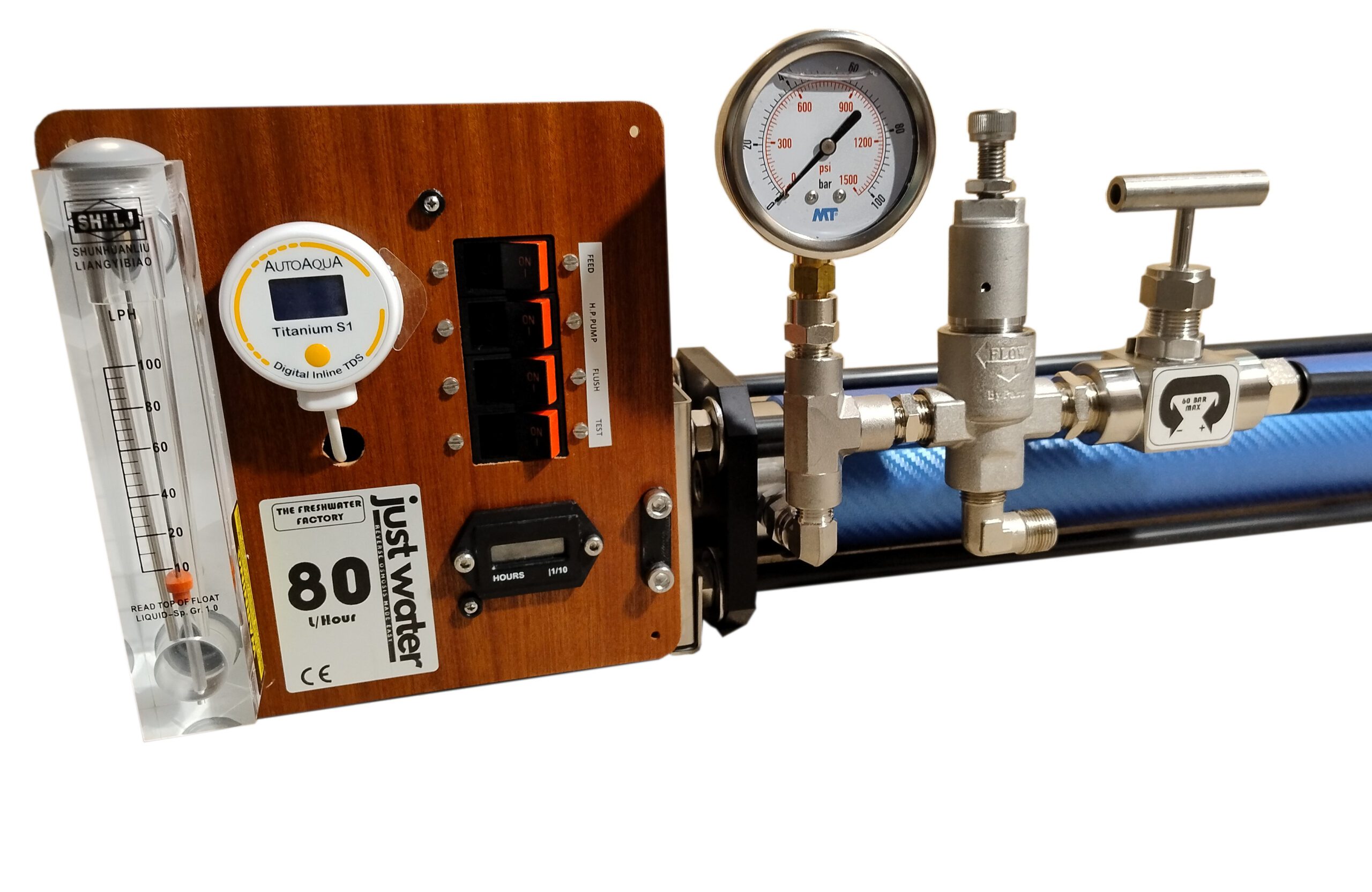
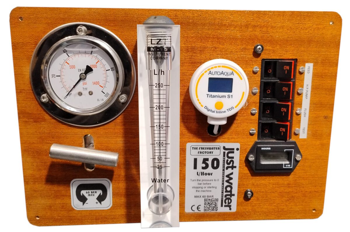
We have finally achieved our goal of simplifying the assembly and the operation of our Blue Gold watermakers. An elegant “All in One” watermaker control panel to have all the controls at your fingertips. This panel, manufactured by an European leading marine instrumentation company, offers increased reliability, reduced factory wiring time and on-board mounting time. It also offers small size and a modern, attractive design and can be integrated into any locations.

The size of the panel is 24 x 15 cm and a depth of 12 cm is needed for mounting.

Water control panel Gauges:

Analogic and digital manometer, visualizing the operating pressure.
Analogic and digital flow meter, visualizing the quantity of the produced fresh water.
Analogic and digital TDS meter, visualizing the quality of the produced fresh water.
Hour counter with animated sand clock.

Watermaker control panel Toggles:

Feed pump toggle.
High pressure pump toggle.
Flushing toggle.
Tank/Test toggle.
Emergency stop button.

Please scroll the pdf document below to find out all the features of this touch screen display for watermakers.

Loader Loading...
EAD Logo Taking too long?

Reload Reload document
| Open Open in new tab

Download [894.35 KB]

Suitable as:

– remote control panel for watermaker
– remote control water
– water control panel
– water maker control panel
– watermaker control panel replacement
– watermaker control panel universal model for almost all marine watermaker brands
– watermaker parts, accessories, components, fittings
– DIY watermaker parts list

We have reintroduced our analog panels starting in 2025, following requests received from many customers who prefer to have this type of device to drive their water maker.

We are working on publishing a simple guide for the use of these panels, which can be used for any water maker, including self-built ones, or to bring old water makers back to life.
It will be ready by the first week of January 2025.

Blue Gold Watermakers JW LIGHT new analogic panel-3 Control panel for watermaker with analogic gauges

Watermaker control panel universal model

Watermaker control panel in Mahogany or Black (carbon look) 4 mm. thickness. It can work with almost any brand of marine watermaker and boat desalinator (or DIY realization).

For those who prefer a traditional board, an analog panel with glycerin pressure gauge and flow meter is available on all our models.

It is complete with:

  • Pressure gauge filled with glycerin
  • Flow meter
  • TDS meter
  • Hour counter
  • Tank-Test outlet switch
  • Flushing switch
  • Feed and High Pressure pumps switches
  • Pressure regulation valve
  • Safety valve
  • Relay box

Sizes: 285 x 200 (110 mm are needed in the rear)

Suitable as:

– remote control panel for watermaker
– remote control water
– water control panel
– water maker control panel
– watermaker control panel replacement
– watermaker control panel universal model for almost all marine watermaker brands
– watermaker parts, accessories, components, fittings
– DIY watermaker parts list